
Untitled. Untitled. TuneTech: Fuel Map and Ignition Map. What is a fuel map or ignition map?
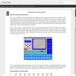
Most of us have heard the term “Mapped ignition” and programmed or mapped injection but may not understand what this actually is. Whilst the engine is running its requirements for fuel and ignition timing will vary according to certain engine conditions, the main two being engine speed and engine load. A “map” is no more than a look up table by engine speed and load, which gives the appropriate fuel or timing setting for each possible speed and load condition. Ignition map. Ignition advance maps. Unit 25 engine and vehicle brief lo1. Unit 25 engine and vehicle brief 4 LO4. Unit 25 engine and vehicle brief 3. Unit 25 engine and vehicle brief 2 LO2. Chassis Dyno Guide - Frequently Asked Questions About Dyno Tests - Hot Rod Network. Over the past decade, chassis dynos have proliferated across the country, in theory making it practical for the masses to evaluate the performance of their engine as installed in the vehicle and compare the results against their buddies’ cars.
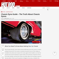
But this assumes that results obtained at a given facility can be directly compared to those from other facilities, and that the results accurately reflect the true power output of the test vehicle. There’s also the question of degree of accuracy, or whether the average dyno shop can adequately evaluate the true effect of small, incremental changes, particularly on late-model, computer-controlled cars. To dig deeper into these issues, HOT ROD contacted leading manufacturers, including Dynapack, Dynojet, Mustang, and SuperFlow; consulted Jeff Burt of TMR, a leading independent dyno expert and test consultant; and took a car to several local dyno facilities for some real-world testing. Read on as we strip the mask off chassis dyno-testing.
Drag Reduction: The Pursuit of Better Fuel Economy. Aerodynamics was first used to increase vehicle performance in race cars during the 1970s.
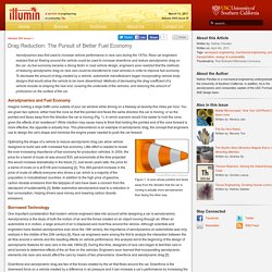
Race car engineers realized that air flowing around the vehicle could be used to increase downforce and reduce aerodynamic drag on the car. As fuel economy became a strong factor in road vehicle design, engineers soon realized that the methods of reducing aerodynamic drag on race cars could be transferred to road vehicles in order to improve fuel economy.
To decrease the amount of drag created by a vehicle, automobile manufacturers began incorporating vehicle body designs that would allow the vehicle to be more streamlined. Methods of decreasing the drag coefficient of a vehicle include re-shaping the rear end, covering the underside of the vehicles, and reducing the amount of protrusions on the surface of the car. Aerodynamics and Fuel Economy Imagine holding a large traffic cone outside of your car window while driving on a freeway at seventy-five miles per hour. Car specifications listed by automobile manufacturer - automobile technical data. Air Resistance Formula. Air Resistance Formula Air resistance is a force that affects objects that move through the air.

Often physics problems used in teaching ignore it, but it is very important for understanding the motion of fast-moving objects like airplanes. It depends on the density of the air, the area of the object, the velocity it is moving, and a "drag coefficient" that accounts for other properties of the object like the surface roughness, and turbulence. Air resistance is also called "drag", and the unit for this force is Newtons (N).
F = force due to air resistance, or drag (N) k = a constant that collects the effects of density, drag, and area (kg/m) Use the notes about Tractive Effort to describe how it alters through altering gear ratios. Untitled. Untitled. LO3 Vehicle Chassis prompt sheet. Untitled. Engineering Explained: 10 Aerodynamic Features Of Race Cars - nissansportz Motorsports News Feed - nissansportz. Posted 04 February 2015 - 05:57 PM Engineering Explained: 10 Aerodynamic Features Of Race Cars There are three main reasons for improving aerodynamics on race cars from a performance standpoint: cooling, downforce, and minimizing drag.
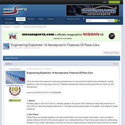
Here are 10 different aerodynamic features starting with the front of the car and working back 1. Splitter A leading edge on the front of the car, relatively parallel to the ground, which attempts to keep high pressure air on top of the car, rather than flowing underneath it. A video about dyno figure manipulation by Motorsport Developments In Blackpool Lancashire.
Vehicle performance performance Level 3. Gas Laws Level 3. Fault diag. Engine Performance Level 3. Angular Velocity. Engine torque, brake power and specific fuel consumption.
Powertrain Performance Graphs - Rototest Research Institute. Rod Length article. Rod Length Relationships You are invited to participate in this attempt to understand a part of internal combustion engines.
I invite any/all criticisms, suggestions, thoughts, analogies, etc.-- written preferred, phone calls accepted from those too feeble or who have arthritis. Contributors are invited to request special computer printouts for specific combinations of interest to them. In general, most observations relate to engines used for some type of competition event and will in general produce peak power higher than 6000 RPM with good compression ring seal as defined by no more than 3/16 CFM blowby per cylinder.
Short Rod is slower at BDC range and faster at TDC range. Long Rod is faster at BDC range and slower at TDC range. A. B. C. D. II. A. B. C. D. A. B. C. D. E. Short Rod -- Min Rod/Stroke Ratio -- 1.60 Max Rod/Stroke Ratio -- 1.80 Long Rod -- Min Rod/Stroke Ratio -- 1.81 Max Rod/Stroke Ratio -- 2.00 Contributors to Date: Bill Clemmons, Jere Stahl. Connecting Rod vs. Stroke Analysis: panic Tech Paper No. 1. Extended Diploma Motor Vehicle Applied Science Level 3.
Applied electronics.