
12V DIY Stirling Generator Plans. The displacer cylinder : The displacer cylinder is made from a stainless steel water pasta container.
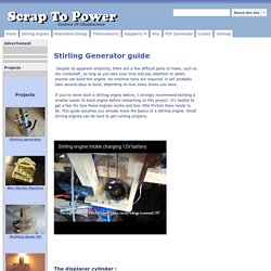
It's about 95mm diameter and cut down to be around 235 mm tall. Stainless steel can hold up to intense heat, and will not corrode easily, so it is a good choice. It's not a good idea to substitute an aluminium container, the performance is abysmal compared to a stainless steel bottle. Keep the lid from the pasta container, you'll need it for the diaphragm. Stirling Engine Home Page -English- Welcome to Stirling Engine Home Page There have been viewers since 5 December 1995.
To Japanese Home Page Do you know about Stirling Engines? The Stirling engine was invented in 1816, before the gasoline and Diesel engines. This page is under construction 5 December 95. Stirling engines for beginners The Stirling engine's structure and history are examined in this session. View of model Stirling engines In this session, I am introducing some model Stirling engines. Let's build model Stirling engines On this page I offer plans for some easy to build Stirling engines. ME422 - Stirling Cycle Machine Analysis (updated 3/30/2013) Stirling Cycle Machine Analysis (Spring 2012)< ME 422 (Class #15543)/ ME522 (Class #15545) = 3 credit hours.
Prereq: MATH344, ME328, CE340, and/with ME412, or Permission The course structure is based on the book 'Stirling Cycle Engine Analysis', I Urieli & D M Berchowitz. (1984). This book is out of print, however some copies are available in Stocker Room 296. Much of the material that is in the book has been updated and placed on this web site, so that you will not need to refer to the text for this course.
The course will develop around the analysis and computer simulation of single phase, piston/cylinder thermal power and refrigeration systems including thermodynamics, heat transfer and fluid flow friction. Requred Course Outcomes Depending on the class size, each student will be responsible for the simulation of a specific machine (engine or refrigerator). Tentative syllabus: There will be no final examination. Ceramic heat cell. A ceramic heat cell, also known as Caloric Porous Structure Cell (CPSC), is a ceramic device to burn a fuel without flame, converting the thermal energy to mechanical work.
In principle any fuel that can be vapourised and pre-mixed with air can be used. "Ultra vaporized steam" replaces the exploding air/fuel mixture as the work medium.[1] The flameless combustion keeps emissions of hydrocarbons, carbon monoxide, and nitrous oxides extremely low. Exhaust gas can be recirculated, which further reduces emissions.[1] A ceramic heat cell made by German firm Enginion is claimed to generate up to 30 megawatts of power per cubic meter, operating at a moderate temperature of 1200 °C, with output varying from 5% to 100% of this, responding in 5 milliseconds. Emissions are claimed to be well below 10 parts per million even without exhaust gas recirculation. . ^ Jump up to: a b c Archive copy of article by Automotive Design and Production, original removed in early 2010.
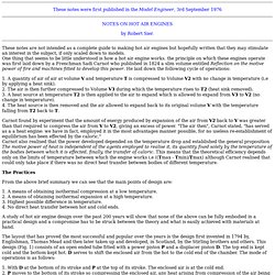
Converging Diverging Nozzle. Instructions Introduction The purpose of this applet is to simulate the operation of a converging-diverging nozzle, perhaps the most important and basic piece of engineering hardware associated with propulsion and the high speed flow of gases.
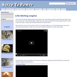
Notes on building model hot air engine. These notes were first published in the Model Engineer, 3rd September 1976 by Robert Sier.
These notes are not intended as a complete guide to making hot air engines but hopefully written that they may stimulate an interest in the subject, if only scaled down to models. One thing that seems to be little understood is how a hot air engine works. the principle on which these engines operate was first laid down by a Frenchman Sadi Carnot who published in 1824 a slim volume entitled Reflection on the motive power of fire and machines fitted to develop this power. He laid down the following cycle of operations: 1. Carnot found by experiment that the amount of energy produced by expansion of the air from V2 back to V was greater than that required to compress the air from V to V2, giving an excess of power.
The Practices From the above brief summary we can see that the main points of design are: 1. 1. 1. The 1 hour LTD Stirling project. Around the side of the ins I used, there is already a line , but I've shown how to mark them in-case your tins don't have a line.
The line should be 5 - 10mm from the bottom of the can, the exact size isn't important.: Now you can cut the tin down to the line that you marked earlier using tin snips(Fig 3a and 3b): The bushing is made from 2.38(3/32")cut to about 15mm long using a knife. To glue the displacer bushing in place straight and true, you need a jig to hold the tube in place, in this engine, it doubles as a flywheel later, to save time. Take some thick cardboard and draw 4 squares 7 cm square each(Fig 8a and 8b).