
AT&T Natural Voices® Text-to-Speech Demo. AVR PCM audio. Simple Arduino audio samples. This tutorial explains how to do simple playback of short (~4 second), low-bitrate (8 KHz) audio samples from Arduino using only a speaker.
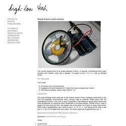
It’s based on the PCMAudio code by Michael Smith. Pre-Requisites You’ll need: An Arduino Uno or DuemilanoveA speaker with wires soldered to it. (Note that a piezo probably won’t work.)The Arduino software, version 0022, 0023 or 1.0 Explanation The audio playback works using two of the Arduino board’s timers, hardware functionality of the AVR (ATmega328) microcontroller that’s normally used to generate PWM output with the analogWrite() function. Download and Install the PCM Library for Arduino Download: damellis-PCM-something.zip Install: Unzip the file.Rename the resulting folder from “damellis-PCM-something” to simply PCM.If it doesn’t already exist, create a folder called “libraries” inside your Arduino sketchbook folder.
Upload the Example Launch the Arduino software. Library Functions Encode Your Own Audio Sample Download: Unzip and run the application. ...KB6.de... Free Drum Samples - Free Downloads - Drum Kit - Wav Samples. Arduino Timer and Interrupt Tutorial. This tutorial shows the use of timers and interrupts for Arduino boards.
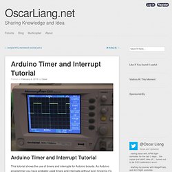
As Arduino programmer you have probably used timers and interrupts without even knowing it’s there, because all the low level hardware stuff is hidden by the Arduino API. Many Arduino functions uses timers, for example the time functions: delay(), millis() and micros(), the PWM functions analogWrite(), the tone() and the noTone() function, even the Servo library uses timers and interrupts. A timer, A.K.A. counter is a piece of hardware built in the Arduino controller. It is like a clock, and can be used to measure time events. The timer can be programmed by some special registers.
The Arduino board is based on the Atmel AVR ATmega168 or the ATmega328 microchip. The most important difference between 8bit and 16bit timer is the timer resolution. 8bits means 256 values (two to the power of 8) where 16bit means 65536 values (two to the power of 16) which is much higher resolution. To summarize: 1. PwmFrequency. Les sorties PWM - La page à JFF. Sur la page de présentation de la Léonardo, il est indiqué qu'il y a 7 sorties PWM en D3, D5, D6, D9, D10, D11 et D13.
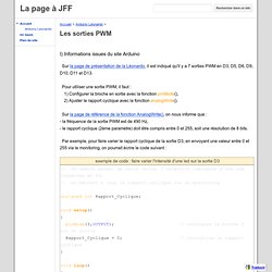
Pour utiliser une sortie PWM, il faut : 1) Configurer la broche en sortie avec la fonction pinMode(), 2) Ajuster le rapport cyclique avec la fonction analogWrite(). Sur la page de référence de la fonction AnalogWrite(), on nous informe que :- la fréquence de la sortie PWM est de 490 Hz,- le rapport cyclique (2ème paramètre) doit être compris entre 0 et 255, soit une résolution de 8 bits. Par exemple, pour faire varier le rapport cyclique de la sortie D3, en envoyant une valeur entre 0 et 255 via le monitoring, on pourrait écrire le code suivant : Voilà, les limites sont atteintes avec la fonction AnalogWrite().Il n'est donc pas possible de configurer la fréquence de la PWM, ni d'utiliser une résolution supérieure à 8 bits.Pourtant le microcontrôleur ATmega32U4 le permet ...
Lab3 - Laboratory for Experimental Computer Science. Arduino Sine wave Generator using the direct digital synthesis Method Here we describe how to generate sine waves with an Arduino board in a very accurate way.
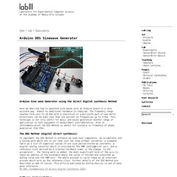
Almost no additional hardware is required. The frequency range reaches form zero to 16 KHz with a resolution of a millionth part of one Hertz! Distortions can be kept less than one percent on frequencies up to 3 KHz. This technique is not only useful for music and sound generation another range of application is test equipment or measurement instrumentation. The DDS Method (digital direct synthesis) To implement the DDS Method in software we need four components.
MT-085: Fundamentals of Direct Digital Synthesis (DDS) Software implementation To run this software on an Arduino Diecimila or Duemilenove connect a potentiometer to +5Volt and Ground and the wiper to analog 0. Results In the upper part of the picture you see PWM signal on pin 11 and in the lower part what the filter makes out of it. DDS Spreadsheet PWM Output lowpass Filter. PlayMelody. Make Noise With The New Arduino Kit!