playground - ShiftBriteLib
Overview Taken from macetech.com. ShiftBrite is a high-brightness LED module containing red, green, and blue elements. It uses a simple clocked serial interface to receive a 10-bit brightness value for each color, resulting in over a billion possible colors.
Project – NPN Power Transistor
A transistor is a semiconductor device commonly used to amplify or switch electronic signals. In this project, a power transistor is used as a digital switch. When pin 9 (digital output) is HIGH, the LEDs will turn on, and when LOW the LEDs will turn off. Using a power transistor with an Arduino pinout will allow you, for example, to control outputs with a higher current or voltage source than Arduino pins support. Use an NPN Power Transistor, one 1k resistor, and 220 Ohm resistors for the LEDs.
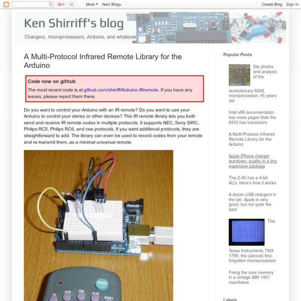
Arduino Tutorial - Learn electronics and microcontrollers using Arduino!
So, I get two or three emails a day, all basically asking the same thing: "Where can I learn about electronics?" In general, most of these people have seen some of my projects and want to be able to build similar things. Unfortunately, I have never been able to point them to a good site that really takes the reader through a solid introduction to microcontrollers and basic electronics. I designed this tutorial course to accompany the Arduino starter pack sold at the Adafruit webshop. The pack contains all the components you need (minus any tools) for the lessons
25+ Alternative & Open Source Database Engines
Almost every web developer has a favorite database that he/she feels comfortable working with as all the tricks & gimmicks are already experienced. It can be one of the popular databases below: or even simpler ones like XML, text, etc. It is understandable why these databases are frequently used; they are well-documented, have a community behind them, integrated with most popular CMSs', easy-to-use, offered by most of the hosting companies ,etc..
ESPEasy - ESP8266
The ESP Easy firmware can be used to turn the ESP module into an easy multifunction sensor device for Home Automation solutions like Domoticz. Configuration of the ESP Easy is entirely web based, so once you've got the firmware loaded, you don't need any other tool besides a common web browser. The ESP Easy firmware is currently at build R78 an looks stable enough for production purposes as long as it's being used as a sensor device. ESP Easy also offers limited "low level" actuator functions but due to system instability, this could be less useful in real life applications. Getting started with the ESP Easy takes a few basic steps.
Online : LED cluster for Arduino testing
My friend Usman and I are collaborating long-distance on an Arduino project. He’s a software guy (by which I mean he’s a guy actually made of software. OK, not really, but almost) and doesn’t have time right now to get up to speed on hardware. So, I send him bits of hardware as needed.
Infrared controlled timelapse photography with Canon DSLRs-Mozilla Firefox
I wished all digital cameras would allow timelapse shooting out of the box. Digital cameras with a selftimer are able to trigger a photo via it's software but for some odd marketing reasons timelapse is seldom added. And even if your camera has a timelapse option it is often limited to 999 shots. You can find lots of remote cable based external timelapse solutions for Canon cameras on the web but I haven't yet seen one that works infrared based. This solution is based on a previous post.
Cheap Arduino Wireless Communications
I was looking for a way to handle wireless communications between two Arduino boards. Other options like Xbee or Bluetooth were going to cost $50 to over $100. Then I found a cheap RF transmitter and receiver at Sparkfun. The total cost is only $9! Here are a few limitations to RF solution: Communications is only one way.
PiDome
The PiDome Home Automation/Domotica project tries to create a transparent home automation platform targeting the Raspberry Pi. It provides a flexible API to add support for custom hardware/services in java. A graphical xml editor is build-in to create devices based on supported protocols. MySensors is supported by PiDome through the SerialGateway or MQTTGateway.. Homepage Install Instructions
A thermocouple datalogger based on the Arduino platform
September 7, 2010 AT 10:11 am A thermocouple datalogger based on the Arduino platform & (previously, rolling your own thermocouples)… It never hurts to collect more data, and I often find myself wanting to record temperatures from a few extra animals.