
LED et calcul de la résistance série. Electro Arduino & co. Composants, capteurs et autres arduino tests. Comment convertir un nombre binaire en nombre décimal. 2 méthodes:La méthode de numération de positionLa méthode du doublement Le système binaire (de base deux) est fondé sur deux chiffres, le plus souvent 0 ou 1.
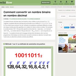
À l’opposé, le système décimal (de base dix) est fondé sur dix chiffres (0,1, 2, 3, 4, 5, 6, 7, 8, ou 9). Pour éviter toute confusion lors de l’utilisation de systèmes numériques différents, la base de chaque nombre peut être spécifiée en la mettant en indice à côté du nombre. Arduino Lesson 4. Eight LEDs and a Shift Register. Arduino includes a special function called 'shiftOut' that is designed specifically for sending data to shift registers.Here is the full sketch, the discussion of how it works follows on from it. /* Adafruit Arduino - Lesson 4. 8 LEDs and a Shift Register */ int latchPin = 5; int clockPin = 6; int dataPin = 4; byte leds = 0; void setup() { pinMode(latchPin, OUTPUT); pinMode(dataPin, OUTPUT); pinMode(clockPin, OUTPUT); } void loop() { leds = 0; updateShiftRegister(); delay(500); for (int i = 0; i < 8; i++) { bitSet(leds, i); updateShiftRegister(); delay(500); } } void updateShiftRegister() { digitalWrite(latchPin, LOW); shiftOut(dataPin, clockPin, LSBFIRST, leds); digitalWrite(latchPin, HIGH); } The first thing we do is define the three pins we are going to use.
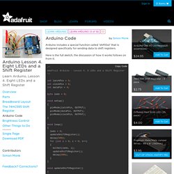
These are the Arduino digital outputs that will be connected to the latch, clock and data pins of the 74HC595. Ajouter des sorties à l'Arduino, le 74HC595. Envoyer un ordre au 74HC595 Nous allons maintenant voir comment utiliser le composant de manière logicielle, avec Arduino.
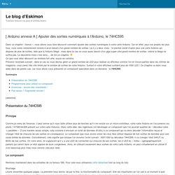
Pour cela, je vais vous expliquer la façon de faire pour lui envoyer un ordre. Puis, nous créerons nous-mêmes la fonction qui va commander le 74HC595. Le protocole Nous le verrons dans le chapitre sur la liaison série plus en détail, le protocole est en fait un moyen qui permet de faire communiquer deux dispositifs. Si jamais vous voulez économiser une broche sur votre Arduino, l’horloge de verrou peut être reliée avec l’horloge de données. Utiliser le composant 74HC595 8 Bit Shift Register avec un Arduino. Introduction Aujourd’hui j’ai fait des recherches sur les matrices de LED afin de pouvoir faire un LED cube 3D de 512 leds (8x8x8) en me basant sur un Arduino.

74HC595 - Shift register. MAX7219 - LED Matrix/Digit Display Driver. RainBoard - RGB LED Rainbow Fader. Before we begin, here is a parts list of everything we will need for this Instructable as well as links to vendors where these items can be obtained.
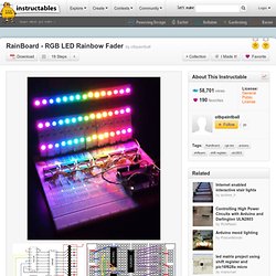
When designing this circuit I made sure to select common components that can be found just about anywhere that sells electronic parts. I found all of the items here on eBay, but many of the standard on-line electronics distributors (Digikey, Mouser, SparkFun etc.) should have these items in stock. I linked to SparkFun parts to make ordering easier. 2x RGB LED Strip - 30 LED/m 1m We need these to make the pretty rainbow effect! 2x Break Away Headers - Straight These are to make the RGB LED strips easy to plug straight into a standard breadboard. Amazon. Quelle est la différence entre un transistor PNP et NPN? Flexible LED Matrix - WS2812B (8x32 Pixel) - COM-13304. I’m a HS computer science teacher with some background in electronics (I built synthesizers when I was in HS 30 years ago) and microcontrollers (2.5 yrs playing with Arduino), and I was able to get this hooked up fairly easily.
There are some things I’ll pass on to other people that might be new to all this that would have made it even easier. I hooked it up using F-M jumper wires on the 3 pins of the male JST connector. 5V and GND went to VCC and GND on a PRT-13032 breadboard power supply stick. I powered the stick with an AC Wall Adapter and with a 9V battery. Did a lot of display testing during a 3-hr period on the 9V battery and didn’t notice any loss of brightness (more below).
From the Arduino, I jumpered GND to the same GND bus the power supply and display were connected to (without this, the display sort of worked, but gots lots of random pixels lighting up), and connected Pin 6 to DIN on the display (the Matrix Library says you can use any pin). Mini Monome. The job of the translator is to take the OSC commands and turn them into serial commands to send to the hardware.
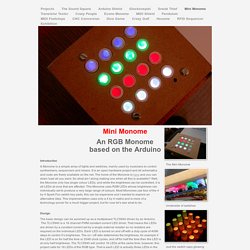
This also looks at the USB port to see if it can find a Monome to pass the data to. It recognises a Monome by it’s USB identifier and in order to get it to recognise the Arduino you either have to hack the translator, or change the Arduino’s USB ID. The translator source code is available but it is quite long and written in a mixture of C, C++ and objective C so it takes some unravelling. The simplest solution is to change the USB ID, this is known as “Flashing” the USB bridge. It will still work with the other Arduino software if you do this, but unfortunately you can only do this using a PC only application, so it’s time Boot Camp earned it’s keep. First you need to download the drivers and the Mprog application onto your Windows partition:- MProg 3.0 > D2XX Drivers > 1/ Install the driver and plug in the Arduino. 2/ When it has all settled down, launch Mprog, Button Pad 4x4 - LED Compatible - COM-07835.
Multiplexing with Arduino and the 74HC595. Multiplexing is a very efficient technique for controlling many components wired together in a matrix/array.
In this example, I'll be talking exclusively about multiplexing an array of LEDs, but the same basic principles apply to other multiplexed components (sensors, buttons, etc). In a multiplexed array of LEDs, only one row of LEDs is on at any given time. It seems like this would limit the types of shapes we can display on the LED matrix, but it actually doesn't. This is because the arduino (or whatever is sending data to the array) is switching through each row so quickly (hundreds or thousands of times a second) that we do not perceive the flashing on and off of each consecutive row.
You can read more about this phenomenon, called persistence of vision, on wikipedia. So how do we send data to one row at a time? Now look at the image below. Make your own 15x10 RGB LED Matrix. Electronic Basics #5: How to Multiplex. Technology Instructables - Offset 59. Amazon.fr Panier. Arduino Ep.1 - Qu'est-ce qu'Arduino? Arduino Ep.18 - Comment utiliser un moteur pas à pas? Introduction au transistor. Arduino - LED Cube 3x3x3 [Full Tutorial]
See Far I.