Arduino camera
20100628ZEROPLUS SCCB 15 EN. Embedded Programmer: Demo: STM32F4 + OV7670 + qSerialTerm. Yup, that mess of wires actually works.
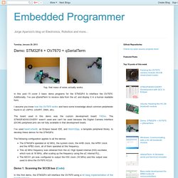
In this post I'll cover 3 basic demo programs for the STM32F4 to interface the OV7670. Additionally, I've use qSerialTerm to receive data from the uC and display it in a human readable form. I assume you know how the OV7670 works and have some knowledge about common peripherals found in uC (GPIO, USART, DMA, etc). The board used in this demo was the custom development board: F4Dev. The STM32F4DISCOVERY wasn't used and can't be used because the Digital Camera Interface (DCMI) peripheral pins are not fully available in that development board. I've used bareCortexM, an Eclipse based IDE, and libstm32pp, a template peripheral library, to develop these demos for the STM32F4. The following configuration applies to all the demos:
Hacking the OV7670 camera module (SCCB cheat sheet inside)
An in-depth look of the OV7670 camera module The OV7670 is a low cost image sensor + DSP that can operate at a maximum of 30 fps and 640 x 480 ("VGA") resolutions, equivalent to 0.3 Megapixels.
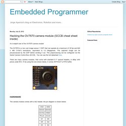
The captured image can be pre-processed by the DSP before sending it out. This preprocessing can be configured via the Serial Camera Control Bus (SCCB). You can see the full datasheet here. There are many camera modules, that come with standard 0.1" spaced headers, in eBay with prices under $10. The camera module comes with a 9x2 header, the pin diagram is shown below: Now, I'll cover the meaning of these pins. **A note about supply voltage and I/O voltage. As stated in the datasheet:VDDA can range from 2.45V to 3.00V.VDDC can range from 1.62V to 1.98V.VDDIO can range from 1.7V to 3.00V. You can (hopefully) see here (sorry, it's buried among other files) the schematic of the model I'm using in this post.
A video is a succession of frames, a frame is a still image taken at an instant of time. YCbCr. Physical Layer Specifications. The Phy Working Group has developed three specifications for high-speed physical layer designs to support multiple application requirements.
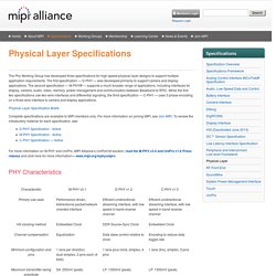
The first specification — D-PHY — was developed primarily to support camera and display applications. The second specification — M-PHY® — supports a much broader range of applications, including interfaces for display, camera, audio, video, memory, power management and communication between Baseband to RFIC. While the first two specifications use two-wire interfaces and differential signaling, the third specification — C-PHY — uses 3 phase encoding on a three-wire interface to camera and display applications. Physical Layer Specification Briefs Complete specifications are available to MIPI members only. For more information on M-PHY and UniPro, MIPI Alliance’s UniPort-M solution, read the M-PHY v3.0 and UniPro v1.6 Press release and click here for more information— www.mipi.org/mphyunipro PHY Characteristics D-PHY Specification Introduction Scope Purpose. Hacking the OV7670 camera module (SCCB cheat sheet inside)
Arduino & Raspberry Pi Camera Interface.
Yes,we learned that we can take mobile phone camera modules from almost all mobile phones to inteface them with our advanced hobby electronics projects just as with any other standard add-on modules.
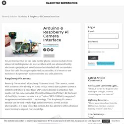
Since this calls for an appropriate microcontroller, it is better to use Arduino or Raspberry Pi microcontroller as a utile platform. Raspberry Pi camera Recently I’ve received a Raspberry Pi camera board. The camera, comes with a ribbon cable already attached to it,is a small size (25mm x 20mm x 9mm) board where a fixed focus 5MP camera module is attached. Part number of the camera module (from OmniVision) is OV5647.
(raspberry pi camera) Raspberry PI comes with two first-rate connectors on board. (Camera Serial Interface) While connecting the camera module to the CSI port (located behind the Ethernet port) of the Raspberry Pi board,ensure that camera cable is inserted in right way, ie the blue strip in the flexible cable is towards the Ethernet (LAN) port. Arduino camera Did You Know?
Rpi Camera Module. Back to the Hub Hardware & Peripherals: Hardware - detailed information about the Raspberry Pi boards.
Hardware History - guide to the Raspberry Pi models. Low-level Peripherals - using the GPIO and other connectors. Expansion Boards - GPIO plug-in boards providing additional functionality.
Embedded Programmer: Hacking the OV7670 camera module (SCCB cheat sheet inside)
