
Raspberry Pi Temperature Sensor. In this tutorial, we will be building a circuit to connect a temperature sensor to our Raspberry Pi, and writing a program to read the sensor data.
The circuit we will build is going to connect to the Raspberry Pi using the GPIO pins. GPIO stands for General Purpose Input/Output. General purpose because all they are is simple connections that can be either high or low, a binary choice. This means we can easily do things that involves binary choices, and it will still be nice and simple to understand what is going on. In this tutorial, we are going to be turning LEDs off and on, and checking whether buttons are being pressed—all very binary actions, which makes them ideally suited for GPIO pins.
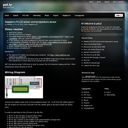
However, this is not all that GPIO pins can be used for. Once we have built our circuit, the next step is to write a program to read the temperature, and give it to us in a nice format. Step One: Updating the Kernel. Raspberry Pi LCD screen and temperature sensor « pel.ly. Items needed Adafruit Pi CobblerHD4470 LCD Character DisplayA DS18B20 temperature sensor ( or - the one I used in this tutorial)4.7kΩ resistor, a full size breadboard or two half size, and a selection of wires.A potentiometer (TRIMMER 10K OHM 0.5W TH) heatshrink tubing, and a soldering iron.And of course, a Raspberry Pi Assumptions.
Jeremy's Blog: Raspberry Pi distance measuring sensor with LCD output. Measure distances from the Sharp GP2Y0A02YK0F sensor using an MCP3008 ADC and hardware SPI.
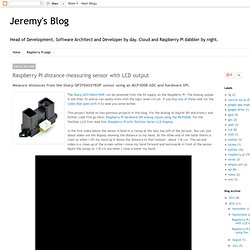
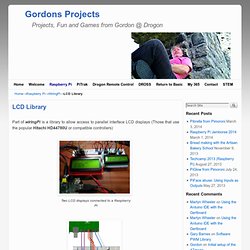
This project builds on two previous projects in this blog. For the Analog to Digital SPI electronics and Python code first go here: Raspberry Pi hardware SPI analog inputs using the MCP3008. For the TextStar LCD first read this: Raspberry Pi with TextStar Serial LCD Display. In the first video below the sensor is held in a clamp at the very top left of the picture. You can just about make out the display showing the distance to my hand. All the code is available on github. I compared this against my sensor by laying a tape measure on the table and looking at the voltage output - it matched perfectly. Raspberry Pi are already evolving - Microcontroller Forum Tracker. Color 1.8" TFT LCD on a Raspberry Pi using Python. Drive a 16x2 LCD with the Raspberry Pi. Whenever you come across a LCD that looks like it has 16 connectors it is most likely using a HD44780 controller.
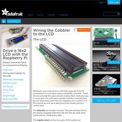
These devices provide the same pinouts making them relatively easy to work with. The LCD uses a parallel interface meaning that we will need many pins from our raspberry pi to control it. In this tutorial we will use 4 data pins (4-bit mode) and two control pins. The data pins are straight forward. They are sending data to the display (toggled high/low). The register select pin has two uses. Adafruit Ultimate GPS on a Raspberry Pi. August 28, 2012 AT 10:33 am aquarat in the Raspberry Pi forums is using the Adafruit Ultimate GPS on a Raspberry Pi, neato!
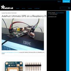
Adafruit Ultimate GPS Breakout – 66 channel w/10 Hz updates. New! Version 3 comes with the latest module which has external antenna support and Pulse-Per-Second output We carry a few different GPS modules here in the Adafruit shop, but none that satisfied our every desire – that’s why we designed this little GPS breakout board. It’s got everything you want and more: -165 dBm sensitivity, 10 Hz updates, 66 channels5V friendly design and only 20mA current drawBreadboard friendly + two mounting holesRTC battery-compatibleBuilt-in dataloggingPPS output on fix>25Km altitudeInternal patch antenna + u.FL connector for external active antennaFix status LED …all for under $40!
The breakout is built around the MTK3339 chipset, a no-nonsense, high-quality GPS module that can track up to 22 satellites on 66 channels, has an excellent high-sensitivity receiver (-165 dB tracking!) Raspberry Pi. Part of wiringPi is a library to allow access to parallel interface LCD displays (Those that use the popular Hitachi HD44780U or compatible controllers)
Binerry, PCD8544 Library for Raspberry Pi. PCD8544 Library for Raspberry Pi (Nokia 3310/5110 Display) For some Arduino/ATmega328p/µC-based projects i’ve used a PCD8544-based Nokia 3310/5110 Display.
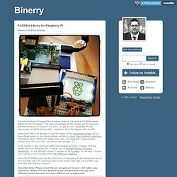
The main advantages of this display are the low price and the simplicity of driving it. Getting Started with Raspberry Pi GPIO and Python « LWK's Arduino Projects. So I’ve been lucky to get my hands on a Raspberry Pi and with my new job at Ciseco I’ve been asked to play around with the GPIO’s and see what cool things we can get them doing.
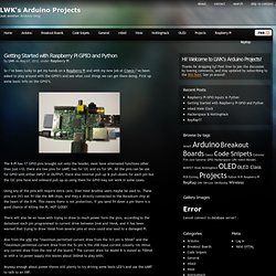
First up some basic info on the GPIO’s. The R-Pi has 17 GPIO pins brought out onto the header, most have alternated functions other than just I/O, there are two pins for UART, two for I2C and six for SPI. All the pins can be use for GPIO with either INPUT or OUTPUT, there also internal pull-up & pull-downs for each pin but the I2C pins have and onboard pull-up so using them for GPIO may not work in some cases. Using any of the pins will require extra care, than most Arudino users maybe be used to. These pins are 3V3 not 5V like the AVR chips, and they a directly connected to the Boradcom chip at the heart of the R-Pi. Anyway enough about power theres still plenty to try driving some basis LED’s and use the UART to talk to an XRF.
So how does one go about talking to the GPIO’s? Installing RPi.GPIO Some Code.