
Michaelkoetter/ArduinoLapse. DIY wired remote control for Canon EOS cameras. The EOS series of cameras from Canon offer a nice feature which is of particular interest for DIYers and technically oriented photographers.
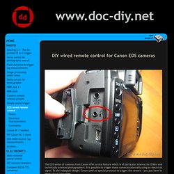
It is possible to trigger these cameras externally using an electrical signal. To the hobbyist's delight Canon used no special protocol to trigger the camera - you just have to short-circuit two wires. Knowing this, building a homebrew Canon RS-60E3 wired remote control clone is a snap! Or maybe an interval trigger, or a microcontroller based... Pinout 350D, 400D, 450D, 500D The external trigger can be accessed with a stereo (3 pole) 2.5 mm jack plug. Connecting the focus-wire (ring) with ground (sleeve) corresponds to pressing the shutter button halfway down and results in focusing the camera. Pinout 20D, 30D, 40D, 50D, 5D... The double and single digit Canon cameras have a different connector (for whatever reason). Electrical characteristics The shutter and focus inputs have the same electrical characteristics and work independently.
Comments. Arduino Multi Kamera IR Control Library for Nikon, Canon, & more. Library Discription: At the search, how to emulate my Nikon IR remote control, I found following site. bigMike.
A first sketch was written fast and with best results. A friend of mine would like use the same easy system to control his Canon. I found the Canon timing and a lot of others at a thread here. Not just Canon, also Minolta, Sony, Olympus and Pentax. Bibliothekenbeschreibung: Auf der Suche im Web nach einer Möglichkeit meine Nikon Fernauslösung zu simulieren, habe ich folgende Seite mit den passenden Informationen gefunden. bigMike. DSLR Remote Controller - Android-Apps auf Google Play. DSLR Controller was the first and remains the best app to fully control your Canon EOS DSLR from your Android device with a USB cable.
No computer or laptop required, no root required, only a compatible mobile device, a compatible camera, and the right USB cable. Compatible camera's and WFT boxes can also be controlled using Wi-Fi (in either Smartphone/Tablet mode or EOS Utility/PC mode). *** DSLR Controller is NOT compatible with all devices! For a free app you can use to test compatibility, see the "Remote Release" app ( ) *** We strongly suggest you read up on the website ( ) about what DSLR Controller can do, how it works, and how to use it, before purchasing. If you need a refund, go to our website ( ). Usage notes, feature lists, device compat. list, changelogs, FAQs, can all be found on our website: Most questions should go to the support and discussion thread at XDA-Developers.com: Features Features include but are not limited to: Requirements.
Building BT Receiver. To build BT Receiver you will need: - An Arduino Board like that: Arduino Pro Mini 328 – 3.3V/8MHz - A USB Host Shield from Oleg Mazurov’s Circuitathome.com site - An compatible bluetooth module like that: Bluetooth SMD Module – RN-42for Bluetooth Module HC-06 check out eBay- Pololu 5V Step-Up Voltage Regulator NCP1402 Solder pin headers to USB Host Shield for Arduino Pro Mini.
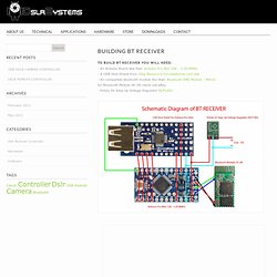
Solder pin headers to Arduino Pro Mini. “Sandwich” where Arduino Pro Mini sits on top of USB Host Mini. Connect Bluetooth module to Arduino Pro Mini ( to programm Arduino VCC to Bluetooth Module must be disconected) Bluetooth -> Arduino RX -> TX TX -> RX +3.3v -> VCC GND -> GND Upload firmware: Firmware upload instruction More will come soon!!! DIY ETTL Flash Cable Extension. IR remote for DSLR cameras. Remote Canon DSLR Video Trigger : Arduino Code. Here is the Arduino code to make the whole thing run.
Credit for the IR remote control code goes to Martin Koch with his thanks to for figuring out the IR code. The code is well commented, but the general idea is this: - The SWITCH pin is set to open input state of HIGH, this is the pin the RF trigger is attached to. . - The state of the Power LED is set to HIGH, and the loop watches for a change from not running to running. Simple as that.
The LED blink code was written from a sample of code I found that allows the LED to blink without using the delay(); function so that no button presses are missed during a delay in the loop. I don't have an AVR programmer, so I used my Arduino to write the code to the atmega328 chip I had simply by pulling the stock chip off my Arduino, inserting the chip I was using for this project, writing the code to it, and swapping it out again.
Void loop() { //run again and again //Serial.print("running"); //uncomment for debugging //Serial.println();