
Gliding flight. Instances of gliding flight[edit] Aircraft ("gliders")[edit] Most winged aircraft can glide to some extent, but there are several types of aircraft designed to glide: In addition to motor gliders, some powered aircraft are designed for routine glides during part of their flight; usually when landing after a period of a powered flight.
These include: Some aircraft are not primarily designed to glide except in an emergency, for example airliners that have run out of fuel. Gliding flight. Skin friction challenge demands active drag control. On all three key fronts in aviation's battle against fuel burn - aircraft weight, engine efficiency and drag - there are promising applications of nanomaterials.

Aircraft paint suppliers explore sharkskin coating. The rough skin of sharks has long been known for the low friction of its myriad tiny, sharp-edged scales.
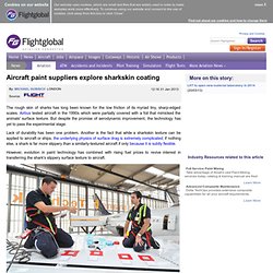
Airbus tested aircraft in the 1990s which were partially covered with a foil that mimicked the animals' surface texture. But despite the promise of aerodynamic improvement, the technology has yet to pass the experimental stage. Lack of durability has been one problem. Another is the fact that while a sharkskin texture can be applied to aircraft or ships, the underlying physics of surface drag is extremely complicated; if nothing else, a shark is far more slippery than a similarly-textured aircraft if only because it is subtly flexible. However, evolution in paint technology has combined with rising fuel prices to revive interest in transferring the shark's slippery surface texture to aircraft.
US coatings specialist PPG is also working on drag reduction surfaces, using paint- and foil-based approaches. Application is a challenge. Skin friction challenge demands active drag control. Powered Lift: Novel GTRI Design Would Let Commercial Jets Use Smaller Airports While Reducing Noise. Related Information > read more Contact Information Lance Wallace Director of CommunicationsGeorgia Tech Research Institute Phone: 404-407-7280 Cell: 404 295-8064 Contact online John Toon.

Circulation control wing. A circulation control wing (CCW) is a form of high-lift device for use on the main wing of an aircraft to increase the lift coefficient.
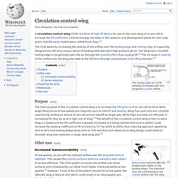
CCW technology has been in the research and development phase for over sixty years, and the early models were called blown flaps.[1] The CCW works by increasing the velocity of the airflow over the leading edge and trailing edge of a specially designed aircraft wing using a series of blowing slots that eject high pressure jet air. The wing has a rounded trailing edge to tangentially eject the air through the Coandă effect thus causing lift.[2] The increase in velocity of the airflow over the wing also adds to the lift force through conventional airfoil lift production.[3] Purpose[edit]
3rd AIAA Flow Control Conference (AIAA) Blown flap. Mechanism[edit] The effectiveness of wings can be greatly improved by using blow-type flow control, while if the intensity of the blown jet is high enough, even the lift predicted by potential flow theory can be surpassed (i.e. the jet flap effect) due to the initiation of supercirculation.[3] Streamwise blowing however can require large amounts of air and energy thus reducing the overall benefits of the flow control solution itself.
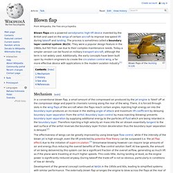
At low speeds, the amount of air being delivered by this system can be a significant fraction of the overall airflow, generating as much lift as if the plane were traveling at much higher speeds. This costs little, during landing at least, as the engine power is significantly reduced anyway. During takeoff the trade-off is not so obvious, particularly in conditions of low air density. Development of the general concept continued at NASA in the 1950s and 60s, leading to simplified systems with similar performance. Lifting-line theory. The Prandtl lifting-line theory,[1] also called the Lanchester–Prandtl wing theory[2] is a mathematical model for predicting the lift distribution over a three-dimensional wing based on its geometry.
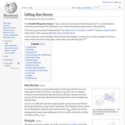
The theory was expressed independently[3] by Frederick W. Lanchester in 1907,[4] and by Ludwig Prandtl in 1918–1919[5] after working with Albert Betz and Max Munk. In this model, the vortex strength reduces along the wingspan, and the loss in vortex strength is shed as a vortex-sheet from the trailing edge, rather than just at the wing-tips.[6][7] Introduction[edit]
A mighty wind - MIT Media Relations. Ion wind. Ion wind, ionic wind, coronal wind or electric wind are expressions formerly used to describe the resulting localized neutral flow induced by electrostatic forces linked to Corona discharge arising at the tips of some sharp conductors (such as points or blades) submitted to high-voltages relative to ground.
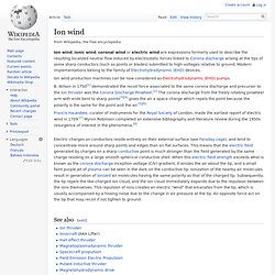
Modern implementations belong to the family of Electrohydrodynamic (EHD) devices. Ion wind production machines can be now considered as Electrohydrodynamic (EHD) pumps. B. Ionocraft. The device is a popular science fair project for students.
It is also popular among anti-gravity or so-called "electrogravitics" proponents, especially on the Internet. The term "lifter" is an accurate description because it is not an anti-gravity device, but produces lift in the same sense as a rocket from the reaction force from driving the ionized air downward. Much like a rocket or a jet engine (it can actually be much more thrust efficient than a jet engine[1]), the force that an ionocraft generates is oriented consistently along its own axis, regardless of the surrounding gravitational field. Claims of the device working in a vacuum also have been disproved.[2] Ionocraft require many safety precautions due to the high voltage required for their operation; nevertheless, a large subculture has grown up around this simple EHD thrusting device and its physics are now known to a much better extent. Ion Thrusters: From Science Fair Experiment to Aircraft Engine?
Electrohydrodynamic thrust, a phenomenon most often seen in student science fairs, may be the key to silent, efficient, and undetectable lightweight aircraft, according to new research published in the Proceedings of the Royal Society.
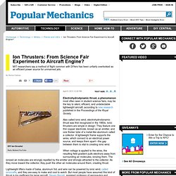
Also called ionic wind, electrohydrodynamic thrust was first recognized in the 1960s. Ionic thrusters are simple in design: They feature one thin copper electrode, known as an emitter, and one thicker tube of a metal-like aluminum called a collector. Plasma actuator. University of Florida professor designs plasma-propelled flying saucer. GAINESVILLE, Fla. — Flying saucers may soon be more fact than mere science fiction. University of Florida mechanical and aerospace engineering associate professor Subrata Roy has submitted a patent application for a circular, spinning aircraft design reminiscent of the spaceships seen in countless Hollywood films.
Roy, however, calls his design a “wingless electromagnetic air vehicle,” or WEAV. Powerful Plasma Actuator for Reduced Drag in Propulsion Systems. The University of Florida is seeking companies interested in commercializing a plasma actuator that reduces drag, helping make aircraft, spacecraft and other vehicles more fuel efficient. The overall speed and efficiency of planes, automobiles and other motorized vehicles is highly dependent on unpredictable circumstances such as fluid eddies, fluctuating temperatures, changes in atmospheric pressure and poor weather conditions. Plasma actuators - engines that use ionized air (plasma) and electric-field gradients to achieve propulsion - can respond to these external factors more rapidly than any other mechanical device. They are also surface compliant and thus much less sensitive to the mechanical failure caused by changes in ambient condition. This robustness is precisely what fuels researchers' strong interest in plasma actuation technology.
Application Plasma actuator for propulsion systems that reduces drag (improves flow control) and requires less power Advantages. On the performance of electrohydrodynamic propulsion. Skip to main page content Proceedings of the Royal Society A: Mathematical, Physical and Engineering Sciencerspa.royalsocietypublishing.org. Glider (sailplane) Single-seat high performance fiberglass DG-800 glider A glider or sailplane is a type of glider aircraft used in the sport of gliding.[1][2] It has rigid wings and an undercarriage.[2] Some gliders, known as motor gliders, are also used for gliding and soaring, but have engines which can be used for extending a flight and, for some types, for take-off.
Aircraft such as hang gliders and paragliders are foot-launched and so are described in separate articles, though their differences from sailplanes are covered below. Glider aircraft that are used for purposes other than recreation, for example for military purposes, do not soar. MIT Daedalus. The MIT Aeronautics and Astronautics Department's Daedalus was a human-powered aircraft[1] that, on 23 April 1988, flew a distance of 71.5 mi (115.11 km) in 3 hours, 54 minutes, from Iraklion on the island of Crete to the island of Santorini.
The flight holds official FAI world records for total distance, straight-line distance, and duration for human-powered aircraft. Eta (glider) The Eta made its first flight on 31 July 31 2000 in Cochstedt, Germany, reaching a height of 2 m (79 in). The second flight was the first aerotow launch, reaching 1,500 m (4,920 ft). The third flight was self powered and had no problems. The official presentation was on 1 August. [citation needed] Glasfaser Nimeta: Eta wings on Nimbus 4 fuselage with motor Three Etas have been manufactured. Vector Force Balance for a Glider.