
Lab3 - Laboratory for Experimental Computer Science. The StepperLab3 stepper motor library is made for our SensorAktor Shield but it works also with other motor driver IC’s like the popular L293.
Compared to the standard Arduino stepper library we added some features for more convenient handling and getting most out of your stepper. The library functions are attached to an interrupt process what allows an accurate speed control and a non blocking behavior. If you tell the motor to go to a certain position this is done in the background while you can do other things in your code. A ramp function allows a acceleration in a given number of steps to the speed which was set before. When you want to move masses with an inertia, a matched acceleration improves the dynamic behavior of your setup. The Half step mode doubles the given step number of your motor. The power control sets the motor current by using the PWM function of pin 9 and 10. Keep in mind that the library is using ATMEGAs timer1 and the corresponding interrupt. Methods Updated 1/12. An “Easy” Brushless Motor Driver Board. Fixing a Chinese Made CNC Stepper Motor Driver Board (TB6560 chips) – Page 2 of 2.
<—- Go to previous Page 1 of 2 Page 2 of 2 —-> See all HomeDIYStuff articles 3.
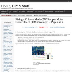
Connecting the CNC Controller Board to the new Schmitt Trigger PCB Now the circuit track to tap into has been identified, we need to connect the wires of the 74HC14 Schmitt Hex Inverter Trigger board you just made. Using the following photograph for reference, CAREFULLY solder A power 5+V supply on the CNC motor driver boardA ground on the CNC motor driver boardA contact for EACH “noisy signal” from corresponding optical isolator outputs (ie: one wire for each axis).A contact for EACH pin 3 track for the Toshiba TB6560 chips (ie: one wire for each axis). A picture is worth a thousand words, so follow this diagram carefully for reference (Fig 6). (Click to enlarge)Fig 6: CNC Controller Board modifications – overall layout 4.
We have to make one cut of the original copper track per axis. (Click to Enlarge)Fig 7: Required circuit track cuts on the CNC Motor Controller Board With this YOU’RE DONE ! 5. Summary. AVR-Based Stepper Motor Driver (STMD) PID Motor Control with an Arduino. PID motor control with an Arduino can be accomplished using simple firmware.
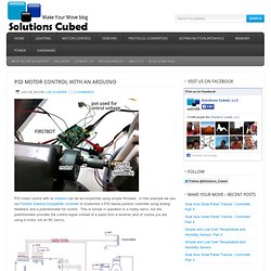
In this example we use our Firstbot Arduino-Compatible controller to implement a PID based position controller using analog feedback and a potentiometer for control. This is similar in operation to a hobby servo, but the potentiometer provides the control signal instead of a pulse from a receiver (and of course you are using a motor, not an RC servo). PID control is fairly common means of controlling a system using a well defined algorithm. You can learn more about the algorithm at Wikipedia (see PID Controller). They are used in industrial control systems of all types. P, I, and D stand for proportional, integral, and derivative. Here’s the code for the equation I used. Here are the major components of the PID detailed. Error Signal- At the heart of PID control is a need to measure an error signal.
PID = Error[0]*PTerm; // start with proportional gain Example: if (Accumulator > 40000) Accumulator = 40000;