
KA/Stay-Alive Devices - Mark Gurries. The process of keeping a decoder running on power after power has been known as a Stay Alive that used the very old Aluminum Capacitor technology to store energy.
Technology has advanced and a new type of capacitor called a Super Capacitor capable of both huge energy storage and do so while supporting high charge and discharge current rating suitable to power a DC motor. The term KA/Stay-Alive will refer to the SuperCapacitor version of the Stay-Alive. The first Super Capacitor KA/Stay-Alive product was introduced by Lenz but was only compatible with Lenz decoders and other DCC manufactures that signed up with Lenz (QSI is one). It has remained a mostly European solution and is expensive.
The first Lenz decoders that supported it were NOT sound decoders. Latter generic KA/Stay-Alive products were introduced by TCS as a direct response to solving power problems with sound decoders. Before the TCS Super Capacitor version Stay-Alive came along, the term "Stay Alive" was used. Why? Why? NO. Roger Amos - PWAyMan. Introduction There are two sorts of analogue electronic controller: closed-loop and pulse-width modulation.
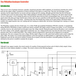
In closed-loop controllers the control knob sets the output voltage, a proportion of which is fed back to the input as a control loop. They have the advantage of quiet operation, but the output transistor can run hot and train starting and slow running, although good (far better than the old rheostat controllers) leave room for improvement. Pulse-width-modulation controllers deliver pulses of full power: the speed control sets the duration of the pulses. At low settings the pulses are brief and the spaces between them correspondingly long.
Electronics « Big-Bytes blog. I recently built myself a backup NAS drive using Windows-7 professional as the OS.
The power profile of this system was simple. Everyday wakeup at 3:00AM and sync up between the shared-drive and backup-drive. I use the task-scheduler to set… For one of my projects i had to use the LTC3526 Boost Switching regulator chip from Linear. It is a great chip. I recently finished building a NAS box to suit my media storage needs. I recently rewound a Hextronik 1300Kv brushless motor (HXM2730-1300), also called “blue wonder”. For my latest project i wanted to use the famous GRBL firmware that loads into an arduino and helps drive steppers with G-code as input.
I had a lot of old style passenger carriers in my HO collection and i wanted to add LED lighting to them. I have a turnigy9x radio that came with a 2.4Ghz module. Recently the USBASP programmer has become a hot favorite to program AVR chips. Having a fine gauge wire is really important with HO scale and finer gauge model railways. Arduino’s AnalogWrite – Converting PWM to a Voltage.
D-A_converter When I first started working with the Arduino platform (it was also my first experience with microcontrollers), I was a little surprised that analogWrite didn’t actually output a voltage, but a PWM (pulse-width modulated) signal.
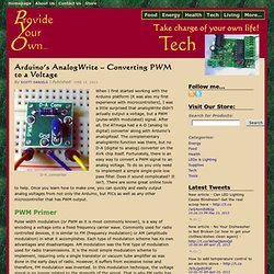
After all, the ATmega had a A-D (analog to digital) converter along with Arduino’s analogRead. The complementary analogWrite function was there, but no D-A (digital to analog) converter on the AVR chip itself. Fortunately, there is an easy way to convert a PWM signal to an analog voltage. To do so you only need to implement a simple single-pole low pass filter.
PWM Primer Pulse width modulation (or PWM as it is most commonly known), is a way of encoding a voltage onto a fixed frequency carrier wave. Simulon Train Controller. Battery Motors and Controllers - FAQs Part 3. Contents, this page: Machines as mixtures of mechanical and electronic systems.
This is a simple section, mainly aimed at novice machine builders such as Robot Wars beginners, but it should also be useful to others. A machine, for the purpose of this discussion is a mechanism of some sort, controlled by maybe a mixture of electronics, hydraulics and other systems. Machines of this sort can seem more complicated than they are, because the beginner has no clear idea of what they need to do.
So the first step is to get some idea of the mechanical task to be done. FAQ sheet index. Machine tools 4QD's controllers can be used in fixed workshop type applications. If you use a modern switch-mode mains supply, the switcher will probably be working at around 100kHz and you will have to consider its performance under full motor current, chopped at 20kHz and the fact that the inductive motor load of the controller can generate nasty over-voltage spikes back into the power supply.
Motor drivers. Instant access to model railway resources without barriers. Are they sitting in the portajohn?
I just finished reading the Model Railroad News review of the new Command and Control Interface from Ring Engineering. It's very similar to the idea presented by the NWSL test sled, containing a 2.4Ghz Radio Decoder, and it completely eliminates the reliance on track based digital signals. In otherwords, you REALLY DO run your TRAINS and NOT your track with RCC! DCC [digital command and control] was based up on DC [direct current]. This new interface is based upon the 2.4Ghz radio signal to deliver that direct Comand and control.
I then propose that we call this new interface protocol "RCC" - Not Radio Command and Control, but rather, Remote Command and Control because this protocol remotely controls each electrical device regardless of how or where it receives it's electrical power. So right now we have a SERIOUS issue of interoperability. Or is the NMRA [and it's members] got their head so far up the DCC "This is the way it must be! "
Direct digital synthesis (DDS) Waveforms. Back emf.