
Fab FM. Companion Website for ARRL Book Ham Radio for Arduino and Picaxe. Tea5767. 555 timer radio. Changes have been made to this instructable, these changes are denoted by asterisks ( * ) A single station 555 timer radio from a few simple and common parts.
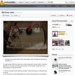
Switches between an oscillator and AM radio receiver. A few things I should warn you about before you get too excited... 1. This is a simple circuit I built by accident, it does not mean it is the best way to build it. 2. I'm still new to circuit mathematics so it have a few problems or calculations that could help find a better solution for this circuit. 3. If you can help me in any way, leave a comment and don't leave comments that don't actually help any other readers reading this instructable.
Also note: I do in fact know the pics are pretty low quality, I'm still getting used to my new camera. Radio receiver circuits & projects. AM Receiver Circuit by P.
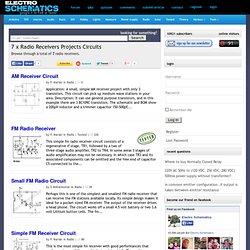
Marian in Radio | Application: A small, simple AM receiver project with only 3 transistors. This circuit can pick up medium wave stations in your area. Description: It can use general purpose transistors, and in this example there are 3 BC109C transistors. FM Radio Receiver by P. This simple fm radio receiver circuit consists of a regenerative rf stage, TR1, followed by a two of three-stage audio amplifier, TR2 to TR4. Small FM Radio Circuit by D Mohankumar in Radio | Perhaps this is one of the simplest and smallest FM radio receiver that can receive the FM stations available locally. Simple FM Receiver Circuit This is the most simple fm receiver with good performances that works great even if the sensitivity is not too high.
Two Transistor AM Radio Receiver This two transistor AM radio circuit is also called “mini-radio”. One transistor FM radio project. My Design A printed circuit board for the original circuit is available through FAR Circuits.
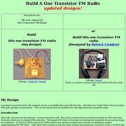
Ask them for "Andy Mitz's One transistor FM radio printed circuit board". The circuit board must be modified for the improved one transistor radio. How to build a very simple FM/AM Receiver using TDA7088 ? I was browsing the Philips website when I came to this IC : TDA7088 and I said wow , it was the simplest AM/FM radio I ever saw.
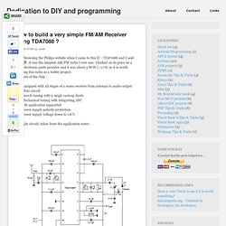
I looked on its price on a local electronic parts provider and it was about 5 RON (~1.7$) so it is worth building this radio as a hobby project. FM Radio Receiver circuit. This simple fm radio receiver circuit consists of a regenerative rf stage, TR1, followed by a two of three-stage audio amplifier, TR2 to TR4.
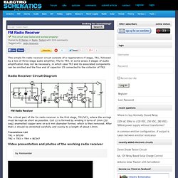
In some areas 3 stages of audio amplification may not be necessary, in which case TR3 and its associated components can be omitted and the free end of capacitor C5 connected to the collector of TR2. Radio Receiver Circuit Diagram The critical part of the fm radio receiver is the first stage, TR1/VC1, where the wirings must be kept as short as possible. Coil L1 is formed by winding 8 turns of 1mm (20 swg) enamelled copper wire on a 6 mm diameter former, which is then removed. TDA7000 FM Radio Receiver Circuit. TDA7000 FM Radio Receiver Circuit Using Tuning Capacitor GENERAL DESCRIPTION The TDA7000 is a monolithic integrated circuit for mono FM portable radios or receivers where a minimum on peripheral components is important (small dimensions and low costs).
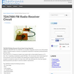
The IC has an FLL (Frequency-Locked-Loop) system with an intermediate frequency of 70 kHz. The i.f. selectivity is obtained by active RC filters. The only function which needs alignment is the resonant circuit for the oscillator, thus selecting the reception frequency. Spurious reception is avoided by means of a mute circuit, which also eliminates too noisy input signals. Special precautions are taken to meet the radiation requirements. The TDA7000 includes the following functions: · R.F. input stage · Mixer · Local oscillator · I.F. amplifier/limiter · Phase demodulator · Mute detector · Mute switch This circuit is typical using with a LM386 for the audio power amplifier. TDA7000 FM Receiver Coils.