
BeagleBoardShoppingList - This page is consistently out-of-date.
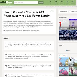
The new home page for this information is: This is a list of all the items that I needed to create my Beagleboard setup. I think this will be helpful to others. Section I: What You Probably Have Already You likely have all of the below. Section II: The Minimalist Kit: What You'll Need But Won't Already Have If you are planning to use the Beagleboard as a Host (i.e. with peripherals like keyboard, mouse, ethernet, etc. attached), then here is a list of how to get started easily. How to Convert a Computer ATX Power Supply to a Lab Power Supply. Edit Article Edited by Abizarl, Krystle C., Jack Herrick, Vertent and 42 others Computer power supplies cost around US$30, but lab power supplies can run you $100 or more!
Online : Ask MAKE: Software for designing circuits. Ask MAKE is a weekly column where we answer reader questions, like yours.
Write them in to mattm@makezine.comor drop us a line on Twitter. We can’t wait to tackle your conundrums! Bjorn writes in: I’m doing my 2nd Arduino project (and 2nd electronics project ever) and am trying to design some of the circuit stuff on computer instead of just wiring it up or scribbling some stuff on paper. Cheap DIY SD card breadboard socket. High voltage joule thief! Tabletop Tesla Coil. The frame of the tabletop Tesla is made entirely of half-inch (12.7 mm) PVC pipe.
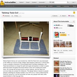
There's no point giving you exact dimensions of the stringers and risers because they depend on how big your secondary coil is. You can scale the frame up or down as you wish. I used a 12 inch long cardboard tube for mine, making the footprint of my coil 14 inches by 11.25 inches. Online : Seven segment display explained. Rotating LED throwies driven by a Stirlingengine (eVoltis Stirli. This is a hot-air machine (stirlingengine), built with some old computer-parts (heatsink and the head of an old harddisk).
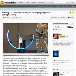
This Stirlingengine (and all others also) works with a temperature difference between the hot bottom side (e.g. heatet with a candle) and the colder topside (cooled with the heatsink of an old 486 CPU) of an metal can (e.g.hairspray).Simplified the engine works as follows: The candle heats up the air in the tin can. Hot air needs more volume. While we have a nearly constant volume in the tin can, the pressure rises up.
Cosmic ray. Robert Hart is developing his own cosmic ray detector using familiar fluorescent tubes and a high voltage(~650V DC) power supply.
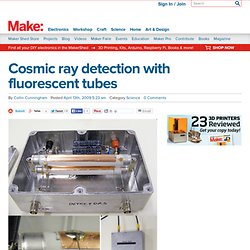
The design is a variation on an example from CERN researcher Sascha Schmeling’s DIY Spark Chamber - Like the CERN example above, when a muon flys through the fluorescent tube, the gas inside ionizes due to the high voltage field across the plates. As a result of the ionization the resistance across the plates will fall slightly and so it should be possible to measure this as a change in current flow in the high voltage source. Radiation originating from Earth will effect the first tube but not the one below it. So singling out matching events between the two should result in the detection of high energy particles sent from a cosmic event — awesome. Online : How-To Tuesday: Teacup Stirling engine. A few weeks ago Gareth had asked me to check out an article from an upcoming issue of MAKE.
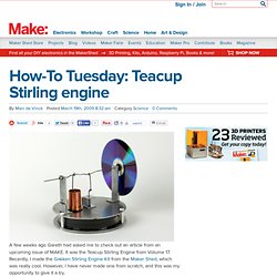
It was the Teacup Stirling Engine from Volume 17. Recently, I made the Gakken Stirling Engine Kit from the Maker Shed, which was really cool. MAKE: Blog: Toolbox: Benchtop power supplies. A benchtop power supply is a handy piece of equipment to have around if you do a lot of electronics or other powered projects on your bench and need a reliable source of power at different voltages (+5V, -5V, +3.3V, +12V, etc).
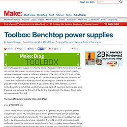
One option is to roll your own, using an ATX power supply yanked out of an old PC. There are a number of how-tos online for doing this. Several of the more popular ones are outlined below. Reverse Surface Mounting method for leadless surface mount devic. This method of surface mounting is unconventional and is not recommended for production projects.
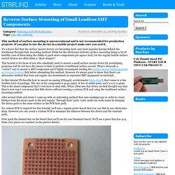
If you plan to use the device in a mobile project make sure you seal it. It's a know fact that the surface mount devices are becoming more and more popular leaving behind the traditional through-hole mounting method. While for the electronics industry surface mounting brings a lot of benefits (one of them being the ability to pack more components per square inch) for the regular hobyst surface mount devices are often times a "show stopper".
My Top Ten Most Useful Breadboard Tips and Tricks. 900,000 volt Van de Graaff Generator using cheap parts. Lets build a 500,000+ volt Van de Graaff generator!!
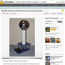
I built this one in about a week, using scrap parts from a sewing machine and materials ordered from I have seen the larger machines in operation at my local science museum and this one does just as well. I have made hair stand on end and even pie pans float up and off the machine. For an explanation of operation go to Wikipedia: ALSO, note that this machine can generate enough static to stop a pacemaker and any other digital device, keep people with heart problems away. Well if your know anything about Van de Graaffs you know that the bigger and smoother the sphere or collector the bigger the charge. The recharge rate or time it takes to build up a charge high enough to jump from the sphere is determined by belt speed and width. This one is an upscale version that I used to test equipment at work and I used the little one to determine the best belt material. Stirling Engine Kit. Headless Computer Display - using PIC18F4550 - Hacked Gadgets -
MAKE: Blog: MAKE it at Home: Table-top linear accelerator. Practical advice on personal development, productivity and GTD - DIY Printed circuit board. I want to share my personal experience with heat toner transfer method of making PCB. It's easy to learn for beginners and it delivers very good result for fair price. Do fast prototyping with fun! Enjoy! ... To get more info about LIQUID TIN see Spec sheet ... NOTE!!! Heat toner transfer is possible because it employs physical properties of laser printer toner. Make A Water Bottle Capacitor. 6 Fantastic Laser Pointer Projects. Burning lasers, keychain lasers, 1000 watt lasers…We love them all. Everyone enjoys the green, red, or even blue glow of lasery goodness.
Make your own Force Sensitive Resistor - HacknMod.com - Amazingl. Controling Electronics using your Parallel Port - HacknMod.com - Do not miss: Ah,the parallel port…25 pins of circuitry goodness. You can manipulate this port to control peripheral electronics by assigning a high or low state (on or off) to each pin. You can also control the port remotely over the internet. The best part is you can use these pins as an input too. This means external, physical control over software is easily possible. Build a simple Marx Generator. MAKE: Blog: DIY Spectroscope. Easy Circuit Board Creation. How To Measure the Speed of Light... Using Chocolate! - Instruct. 3D Magnetic Field Viewer: Test the viewer - Instructables - DIY,