
Guitar preamp tone control circuit with IC TL072 – Free Electronic Circuit Schematics. Preamp tone control circuit The preamplifier circuit is shown in the figure has some interesting features that separate it from “normal,” assuming there is such a thing. The circuit is built by a TL072 amplifier. This is a simple design and provides excellent tonal range. The gain structure is designed to provide a huge amount of profit, which is ideal for guitarists who want to sound completely distorted “fat”. This is an image of the circuit. The preamp uses a dual op amp that amplification only. As shown in the figure, with a classic guitar input, you can get very big overdrive sound by winding volume, then setting the master to an appropriate level.
If you use the TL072 op amp as shown, you can see that noise is a problem, especially at high gain with lots of treble boost. Balanced Audio Amplifier Schematic & PCB – Free Electronic Circuit Schematics. Free circuit dot com is still present about audio amplifier circuit ,today, We’ll like to show you about Electronically balanced XLR inputs for audio amplifier circuit that i had designed from learning with “Crown LPS2500 ” amplifier circuit.
Balanced connections with connectors of the three conductors, usually the XLR or TRS. XLR microphones for example, often used because of its durable construction, while TRS plugs are generally used for inputs and outputs of the mixer due to its low profile. We have take the XLR inputs, Speaker and binding post outputs, stereo/parallel/bridge-mono mode, power/fault/signal presence/clip indicators, forced-air cooling; and protection against shorts, no-load, on/off thumps and radio-frequency interference. You don’t worry to build this project as we have schematic and PCB completely . Balanced audio circuit Balanced audio topside PCB Balanced audio Top-side PCB Posted in Audio amplifier , Power amplifier , Sound . Library. Electronics Circuits: Unbalanced to Balanced Line Converter.
This circuit will convert unbalanced audio lines to balanced audio lines.
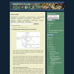
Here's the schematic diagram using NE5532 dual opamp chips, some resistors and capacitors. We all know that balanced lines have less susceptibility to noise, especially on long distances. This is common knowledge.But I'd like to point out one more benefit of balanced signals that I just realized this afternoon. And that benefit is you'll have 6db more gain in a balanced signal compared with the original unbalanced signal!!! Mathematically, we know it would happen, but seeing it as a real waveform in Sonar is proof of concept. What's the big deal about 6db gain? You see, MOST gear are really unbalanced inside. But he also said that there are some truly balanced circuitry where you can't take away any part out, and these are almost always the best kind of gear. Back to the topic... the circuit above can be added to any unbalanced out and make it balanced. DRV135 datasheet, Pinout ,application circuits Audio Balanced Line Drivers.
Sound System Interconnection. Rane Technical Staff RaneNote 110 written 1985; last revised 7/11 Cause and prevention of ground loops Interfacing balanced and unbalanced Proper pin connections and wiring Chassis ground vs. signal ground Ground lift switches Introduction This note, originally written in 1985, continues to be one of our most useful references.
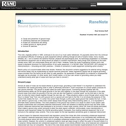
It's popularity stems from the continual and perpetual difficulty of hooking up audio equipment without suffering through all sorts of bizarre noises, hums, buzzes, whistles, etc.-- not to mention the extreme financial, physical and psychological price. Rane's policy is to accommodate rather than dictate. Ground Loops Almost all cases of noise can be traced directly to ground loops, grounding or lack thereof. A second reason for balanced interconnect's bad reputation comes from those who think connecting unbalanced equipment into "superior" balanced equipment should improve things. The Absolute Best Right Way To Do It Figure 1a.
Figure 1b. Figure 2. Figure 3. Summary.