
HowTo Calibrate, Tune and Fine Tune your printer and filament - No category - Talk Manufacturing. Stephan schulz. For a project I wanted to have fluorescent light tubes turn while they were powered up.
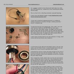
I needed four wires connecting the ballast with the tubes. This is a How-To for a Slip Ring Connector using ball bearings. (I have more and detailed images at www.stephanschulz.ca/sts/howto/newSlipring/index.html) "A slip ring (in electrical engineering terms) is a method of making an electrical connection through a rotating assembly. " Slip ring connector.
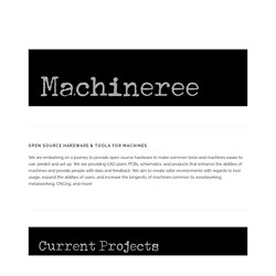
Machineree. Hot wire cutter plans and build from simple materials and cheap parts!
This particular hot wire cutter utilizes 28 guage nichrome wire, a PWM controller, and adjustable fence. The wire temperature is controlled via the knob and indicator states whether it is on and off. The 20A HHO PWM controller for this circuit can be found easily. 3D design Custom Font Text Generator. 2,100 Mechanical Mechanisms. [Nguyen Duc Thang]’s epic 2100 Animated Mechanical Mechanisms is one of the best YouTube channels we’ve ever seen.
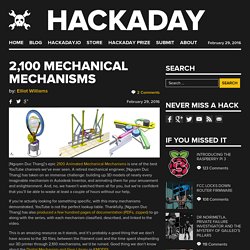
A retired mechanical engineer, [Nguyen Duc Thang] has taken on an immense challenge: building up 3D models of nearly every imaginable mechanism in Autodesk Inventor, and animating them for your amusement and enlightenment. And, no, we haven’t watched them all for you, but we’re confident that you’ll be able to waste at least a couple of hours without our help. If you’re actually looking for something specific, with this many mechanisms demonstrated, YouTube is not the perfect lookup table. Thankfully, [Nguyen Duc Thang] has also produced a few hundred pages of documentation (PDFs, zipped) to go along with the series, with each mechanism classified, described, and linked to the video.
Thanks [alnwlsn] for the tip! Spanner Jaw Sizes. This page has a useful chart for comparing spanner sizes (a wrench in the USA) and common nut/bolt use.
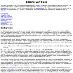
Although it is believed to be correct, use the suggestions and data provided on this web page at your own risk! Please read the disclaimer first. From here you can just jump directly to the Jaw Size Table but I think you should read the whole page at least once for advice (or twice if you are a judge for the "most boring web page" competition). Here is the table of contents: Background Using The Table Selecting Spanners Safe and Correct Use The Jaw Size Table References Acknowledgements Disclaimer Home to PSC's Page Background For the 'British' sizes, the nut/bolt size corresponds to the spanner marking (i.e. a 1/2" W spanner fits a Whitworth bolt with a shank/thread diameter of 1/2"). The BA (British Association) sizes were formulated in 1884 and standardised in 1903. Using the Table The table was created from a spreadsheet. Selecting Spanners Safe Use DO: Use the correct fitting tool. KMODDL - Kinematic Models for Design Digital Library.
Plastics Machining and Fabricating: Feature. Feature Stories Archive Clear Plastics Display Advantages Industry leaders compare and contrast Acrylic and polycarbonate.

Which material is the top choice?
Model engineering. Ac motors. StructuralAnalysis. Interactive geometry. Helpful Hints – part 3 « Start Model Engineering. George Neill, retired engineer and Quality Manager for CAA and FAA In support of my efforts in assisting newcomers to model engineering I have recently received a number of excellent articles prepared by George Neill, a retired professional engineer from Fareham, Hampshire.
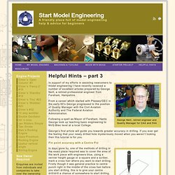
From a career which started with Plessey/GEC in the early 60′s George progressed to the position of Quality Manager with the Civil Aviation Authority and The Federal Aviation Administration. Following a spell as Mayor of Fareham, Hants George took up teaching basic engineering to NVQ Btec level at a local College. George’s first article will guide you towards greater accuracy in drilling.
If you ever get the feeling that your newly drilled hole mysteriously moved when you weren’t looking then this tutorial is for you.
A Woodworker's Guide to Tool Steel and Heat Treating. A Woodworker’s Guide to Tool Steel and Heat Treating Ever wonder by what magic steel can be made either hard or soft?
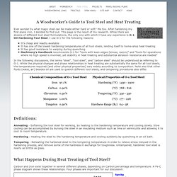
Me too. After hardening my first plane iron, I decided to find out. This page is the result of my research. While there are dozens of different tool steel formulations, the only one with which I have any experience is O-1 Oil Hardening Tool Steel. It’s cheap and readily available It has one of the lowest hardening temperatures of all tool steels, lending itself to home-shop heat treating It has good resistance to warping during quenching Machinery’s Handbook recommends O-1 for "tools with keen edges (knives, razors)" and "tools for operations where no high speed is involved, yet stability in heat treating and substantial abrasion resistance are needed" In the following discussions, the terms "steel", "tool steel", and "carbon steel" should be understood as referring to O-1.
Definitions:
Drill Sharpening. Sharpening Drills (by Colin Binnie) Explaining the geometry of a twist drill via the internet is a bit like describing a spiral staircase in unambiguous Patagonian prose.
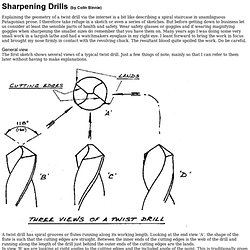
I therefore take refuge in a sketch or even a series of sketches. But before getting down to business let us consider at least the sensible parts of health and safety. Wear safety glasses or goggles and if wearing magnifying goggles when sharpening the smaller sizes do remember that you have them on. Many years ago I was doing some very small work in a largish lathe and had a watchmakers eyeglass in my right eye. General viewThe first sketch shows several views of a typical twist drill. A twist drill has spiral grooves or flutes running along its working length. Drill in action When a drill is cutting, the material nearest the centre of the drill is literally pushed or smeared aside by the ridge at the end of the web until it comes within the sweep of the cutting edges. Now look at the sketch of the finish position.
Cnc. Cad/cam. PID controllers.