
Driver - How can I efficiently drive an LED? ZXLD381. Constant current LED driver circuits - Designing with LEDs. Roundup: Driving, dimming, and protecting LEDs – A list of DIY circuits and articles for LED power and control.
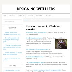
FET Constant current drivers for LED display using BF256. FET Constant current drivers for LED display using BF256 This is a FET Constant current drivers circuit for drive LED display which can use FET-BF256 instead resistor so well.
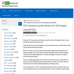
Normally when you use LED display in any circuits often use a resistor for limit LED current. Because easy and cheap. But it is not best, this way is ideal for the stable voltage source only. When we change voltage source, the current that flow through the LED will also changes, causes LED not stable brightness. A current source based on a JFET. In Lecture 1 we introduced the idea of a current source, and mentioned that these were slightly more difficult to implement than the perhaps more familiar voltage source.
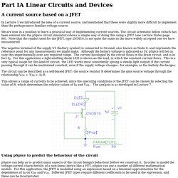
We are now in a position to learn a practical way of implementing current sources. The circuit schematic below (which has been entered into the pSpice circuit simulator) shows a simple way of doing this using a JFET (see Lecture Notes page 86). Note that the symbol used for the JFET, type 2N3819, is not quite the same as the more widely accepted one we have encountered! The negative terminal of the supply V1 (battery symbol) is connected to Ground, also known as Node 0, and represents the reference point for any measurements we might make. Although the battery voltage is indicated as 5V, pSpice will let us vary this experimentally over any required range. Battery repair. High-Power Control: Arduino + N-Channel MOSFET. Eventually you are going to find yourself holding a 12v solenoid, motor, or light and wondering “How the heck am I supposed to control this from my Arduino?”
And we have covered this in the past. Today we are going to talk about another way of doing just that, this time with an N-Channel MOSFET metal–oxide–semiconductor field-effect transistor, specifically the RFP30N06LE MOSFET (You can pick these up from sparkfun). but you can use any N-Channel MOSFET exactly the same way. How this works WARNING: I am about to simplify the crud out of this, so beware… it is here in an attempt to explain, in simple terms, what is going on. Microcontroller - Arduino/Atmega with TIP120/121/122 transistors: base current question.
TIP120 transistor resistor calculation. Arduino UNO Tutorial 6 - Rotary Encoder. Ronja Guidelines. PC SOUND-CARD SCOPE INTERFACE FACILITATES DC RESTORATION. Waveform before correction The 555 Timer IC when operated as an astable oscillator from 5V provides a square wave of 0-5V and the waveform at the timing capacitor varies from 1/3 to 2/3 of 5V. The first screen shot shows the timer IC 555 AC coupled waveforms as captured by the PC sound-card. It can be seen that the zero settles at the average value. (The input has been scaled by 1:10 to remain within the input voltage limits.) The square wave shows a peak value of 171mV instead of 5V and the capacitor waveform appears to be centered at 0V with a peak value of 66.59mV. The interface circuit provides two peak-hold circuits which provide the positive and negative peak DC value of the input waveforms. ExpressPCB - Free PCB layout software - Low cost circuit boards - Top quality PCB manufacturing. Physical Computing. Hall Effect Current Sensors, Hall Current transducers, Converters, Closed Loop Hall Sensors.
CLAMP METER, WITH FREQUENCY - 72-7224 - TENMA.
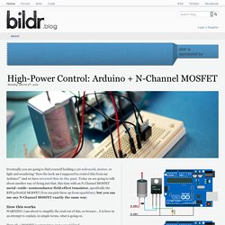
Model electronics. Car electronics. Charlieplexing. Charlieplexing is a technique proposed in early 1995 by Charlie Allen at Maxim Integrated[1] for driving a multiplexed display in which relatively few I/O pins on a microcontroller are used to drive an array of LEDs.
The method uses the tri-state logic capabilities of microcontrollers in order to gain efficiency over traditional multiplexing. Although it is more efficient in its use of I/O, there are issues that cause it to be more complicated to design and render it impractical for larger displays. These issues include duty cycle, current requirements and the forward voltages of the LEDs. A Charlieplexed digital clock which controls 90 LEDs with 10 pins of a PIC16C54 microcontroller. Click to enlarge picture.[2] Traditional multiplexing[edit] Display multiplexing is very different from multiplexing used in data transmission, although it has the same basic principles. Charlieplexing[edit] 1 A LED簡介 原理 2008 1. Charlieplexing.
Power supply. Reflow Skillet. Skill Level: Beginner by Nate | July 01, 2006 | 47 comments I've been reflowing SMD parts on PCBs for around a year now.
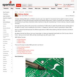
Spark Fun has barely had the capitol to invest in a hot-air rework station, let alone pick and place machines and industrial reflow ovens. Luckily, as business has increased, revenue has allowed us to purchase a few bottom-dollar machines to help with manufacturing. I'm here to tell you, it was all a waste of money...
Don't get me wrong, there is the correct way to manufacture 10,000 units of a caller-ID controller board, and then there is the Spark Fun way. Here is a tutorial that will break down the different approaches to SMD reflow soldering, what we've learned, and what to steer clear of. As always, this stuff can kill you, burn your house down, or make your basement smell pretty foul. SMD Reflow Tutorials: There are five ways to solder SMD parts that I can think of: