
Keep an Eye on Your Fermenting Beer with BrewMonitor. RF transceivers. Minne4 Hall sensor - Minne4 Hall sensorv1.0.pdf. Group thirteen senior design two final paper.pdf. Measuring Current with the Arduino. Although there are dedicated sensors to measure current - such as the Allegro Microsystems ACS712 (as used in my Power Supply Project), this article describes the more "traditional" method using a low value shunt resistor.
Using a shunt provides a lot more flexibility in the current range that's available, rather than being "stuck" with the 5A or 30A ranges of the dedicated Hall Effect sensors. Converting current into voltage The Arduino's analogue input pins measure voltage (generally between 0 and 5 volts) so how do we convert current into volts? Thanks to Ohm's Law, there's a very simple linear relationship between the current flowing through a circuit and the voltage applied to the circuit. Ohm's Law states that the current flowing through a conductor between two points is proportional to the volage difference across those points. For example, if we have a known, fixed, resistance of 2 Ohms and we apply 6 volts across it, then the current flowing through it must be 6 ÷ 2 = 3 amps. 1.
Allegro ACS712 current sensor. Increases the rise time of the sensor output, and therefore, sets the bandwidth of theinput signal.
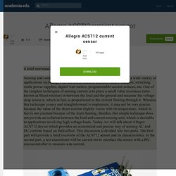
The maximum bandwidth of the input signal is 80 KHz at zero externalfilter capacitor. The bandwidth decreases with increasing C. Allegro ACS712 current sensor. Voltmeter and Ammeter using PIC Microcontroller. Voltmeter and Ammeter can be easily made using PIC Microcontroller having ADC (Analog to Digital Converter).

I am using PIC16F877A and the result is displayed on an LCD Display. PIC16F877A is enough if you do this project only for testing purposes. I suggest to use PIC with low pin numbers and multiplexed 7 segment display if you wish to use this as your measuring instrument. If you don’t know the basis of PIC ADC and LCD Interfacing please read the following articles.
ADC module of PIC Microcontroller converts the Signals on its analog pin to 10 bit binary data and it has software selectable high and low voltage reference input to some combination of VDD, VSS, RA2 and RA3. BOLT 18F2550 SYSTEM PIC PROJECTS PROGRAMMING SOFTWARE HARDWARE MANUAL PROGRAMMING MANUAL GETTING STARTED MANUAL OF BOLT 18F2550 SYSTEM PUNTO FLOTANTE S.A. Antennas.
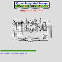
Test & Measurement. Google Image Result for. Google Image Result for. Attachment.php (JPEG Image, 800 × 545 pixels) Tcmt1100.pdf. 6N137.fm - 6N137.pdf. 4n35.pdf. Virtual Integrated Design, RS-232 electrical isolation circuit, free! RS232 Electrical Isolation Circuit Home Applications.
MouseController. Nuts and Volts - May 2012 - Page 40-41. Serial Communication RS232 & RS485. High- Frequency Transistor Amplifier Calculator. Common-Emitter and Common-Collector Transistor Amplifier Calculator for High-frequency Operation Analysis of the bipolar transistor amplifier at low-frequency is relatively easy, and several calculators exist online that do a good job.
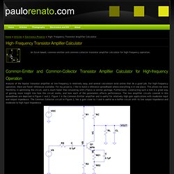
For high-frequency operation, there are fewer references available. For my projects, I like to build a reference spreadhseet where everything is in one place. This allows me more flexibility in optimizing the circuit, and is much faster than simulating with LTSpice or similar package. Furthermore, constructing such a tool is a great way of gaining more insight into how the circuit works, and how each of the parameters affects performance. Combining Multiple Resistors to Improve Tolerance. Combining Multiple Resistors to Improve Tolerance Series and parallel resistor combinations are one of the first things you learn when studying introductory electronics theory (see Figure 1).
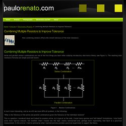
The resulting total resistance formulas are simple and well known. Figure 1 - Resistor Combinations A much more interesting, and as we will see more difficult problem, is the following: "What is the Tolerance of the series and parallel combinations given the Tolerance of the individual resistors? " Resistors. Topics Back to Contents .What do resistors do?
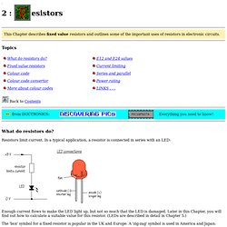
Resistors limit current. In a typical application, a resistor is connected in series with an LED: Enough current flows to make the LED light up, but not so much that the LED is damaged. The 'box' symbol for a fixed resistor is popular in the UK and Europe. Resistors are used with transducers to make sensor subsystems. Microphones and switches are input transducers. In other circuits, resistors are used to direct current flow to particular parts of the circuit, or may be used to determine the voltage gain of an amplifier. Most electronic circuits require resistors to make them work properly and it is obviously important to find out something about the different types of resistor available, and to be able to choose the correct resistor value, in.
Class A Amplifier - Class-A Transistor Amplifier Tutorial. The Class-A Amplifier Common emitter amplifiers are the most commonly used type of amplifier as they have a large voltage gain. They are designed to produce a large output voltage swing from a relatively small input signal voltage of only a few millivolt’s and are used mainly as “small signal amplifiers” as we saw in the previous tutorials. However, sometimes an amplifier is required to drive large resistive loads such as a loudspeaker or to drive a motor in a robot and for these types of applications where high switching currents are needed Power Amplifiers are required.
The main function of the Power Amplifier, which are also known as a “large signal amplifier” is to deliver power, which is the product of voltage and current to the load. Because of these high load currents the output transistor(s) used for power amplifier output stages such as the 2N3055 need to have higher voltage and power ratings than the general ones used for small signal amplifiers such as the BC107. The r.m.s. RS232 Expander. Simple hardware expands PC's COM port from COM1 to COM1/1 and COM1/2.
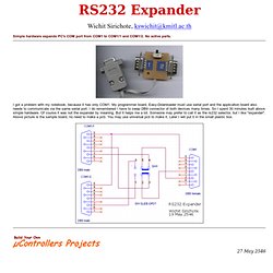
No active parts. I got a problem with my notebook, because it has only COM1. My programmer board, Easy-Downloader must use serial port and the application board also needs to communicate via the same serial port. I do remembered I have to swap DB9 connector of both devices many times. So I spent 30 minutes built above simple hardware. Isolated RS232C for PIC18F84. Another method that helps program development besides a dot LED as the output device is a serial bit.
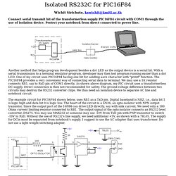
With a serial transmission to a terminal emulator program, developer may then test program running easier than a dot LED. One of my circuit uses PIC16F84 having one bit for sending ascii character with "printf" function. The PIC16F84 provides a very convenient way of connecting serial data to terminal. We may use a 1K resistor connects RB1, say to RxD pin of COM1 directly. Isolated Full-duplex Rs232 Interface. The isolator is intended to provide electrical isolation between a computer and the equipment connected to its serial port.
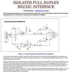
This can be necessary when the target system works at a completely different voltage level, or when earth loops must be avoided. Figure 1 shows how the electrical isolation is achieved. Connector K1 is linked to the serial port of the PC, power to the PC side of the circuit is derived from the signal lines DTR and RTS. Build Your Own Microcontroller Projects. EP&T - Electronic Products and Technology - Canada's Leading Electronics Website. Photosensitive materials - Tech Place. PIRSensor-V1.2.pdf. NL11NH.pdf. RE200B.pdf. High Performance PIR Motion Detector IC - BISS0001.pdf. PIR (motion) sensor ID: 189 - $9.95. PIR Motion Sensor Tutorial. Pyroelectric ("Passive") InfraRed sensors: '''What is a PIR sensor? ''' PIR sensors allow you to sense motion, almost always used to detect whether a human has moved in or out of the sensors range.
They are small, inexpensive, low-power, easy to use and don't wear out. For that reason they are commonly found in appliances and gadgets used in homes or businesses. They are often referred to as PIR, "Passive Infrared", "Pyroelectric", or "IR motion" sensors. PIRs are basically made of a pyroelectric sensor (which you can see above as the round metal can with a rectangular crystal in the center), which can detect levels of infrared radiation. Along with the pyroelectic sensor is a bunch of supporting circuitry, resistors and capacitors. For many basic projects or products that need to detect when a person has left or entered the area, or has approached, PIR sensors are great. Some basic stats These stats are for the PIR sensor in the Adafruit shop which is very much like the Parallax one.
Thermal Flashlight Using MLX90614 IR Evaluation Board From Sparkfun. What I want to do I would like to build a Thermal Flashlight that is very similar to the current recommended method on- only instead of wiring in a standalone IR sensor, I would like to use the Evaluation Board for MLX90614 IR Thermometer from Sparkfun. The advantage of using the evaluation board over the standalone component is the board includes its own ATMega328 chip.
In other words, you don't need to connect it to an Arduino Uno because it already has one embedded into it on a much smaller footprint. This should make it much easier to do what this guy was trying to do on Instructables- only without having to stuff an entire Arduino Uno into the flashlight body. Gate Alarm. Circuit : Rev Thomas ScarboroughEmail :scarboro@iafrica.com. Home controller - Intro of Time Scheduler and Regulator modes. Schmitt Trigger. Circuit : Andy CollinsonEmail : Description This circuit uses a single op-amp and the output is triggered by two different voltage levels. Circuit : The schmitt trigger circuit is built around a single LM741 op-amp, its output buffered by a transistor, which in turn energizes a relay.
The relay may be replaced by a red LED if desired. Voltage Comparator Switch. Small General Purpose Audio Test Set. Circuit : Rodney Byne, UKEmail : CXI Schematics on Circuit Exchange International. Transformers. Introduction Transformers have been an essential component in electrical and electronic circuits since the 1830s and although new technologies in some electronic circuits have reduced the need for transformers, they are still essential in many applications.
How Transformers work. This module describes how transformers work, and how the design of both the transformer coils, and the core on which they are wound affects the efficiency of the transformer. Detailed descriptions of many types of transformer are also given together with typical applications. Diode Tutorial & How to build an AC to DC power supply. Make PCBs at home with magazine paper and your laser printer. Analog Electronics: Basic Circuits of Operational Amplifiers. » PIC18F2550 KS0108 Graphical LCD Oscilloscope semifluid.com. PIC-MICRO-WEB THE LOWEST COST TCP IP WEB SERVER FOR PIC MICROCONTROLLERS $39/ea IN SINGLE QUANTITY. Hacktronics. What is .NET Gadgeteer? - Gadgeteer - FrontMotion Firefox. Few LM317 Voltage regulator circuits that has a lot of applications. Few LM317 voltage regulator circuits. AllPinouts - Connectors, Cables and Adapters Pinouts. PIC18F.COM – Tutorials and Sample Code.
Microchip PIC Tutorials Archives. Resistor Color Codes & Component Identification. Resistor Color Code Bands& Other Component Identification Resistor Color Code Identification While these codes are most often associated with resistors, then can also apply to capacitors and other components. The standard color coding method for resistors uses a different color to represent each number 0 to 9: black, brown, red, orange, yellow, green, blue, purple, grey, white. On a 4 band resistor, the first two bands represent the significant digits. On a 5 and 6 band, the first three bands are the significant digits. PIC USB Development Board. From WFFwiki Since I wanted to do some USB development work with the PIC18F4550 and PIC18F2550 board (for projects like my C64 VICE front-end and Atari joystick adaptor) I needed a USB reference board to develop the software.
Open Source Visual C++ Class for USB Generic HID Communication. Open Source Framework for USB Generic HID devices based on the PIC18F and Windows. Home. Building a PIC18F USB device - WFFwiki. Eremex. Usbpicprog. USBPicprog Open Source programmer. Inspiring Creations. Pic 18f4550. Microchip Controller Area Network (CAN) Bit Timing Calculator - MCP2510, MCP2515, & PIC18F; Legacy & ECAN Controllers. PIC 18F4550 USB 16F877A IO RS232 Eval Board. Microcontroller Projects: PIC 18F4550 USB IO (Input / Output) Board with Analog. Lab 13: Read and Write to internal EEPROM. Fox Delta Dual Channel SWR meter by I2TZK - swm2-doc.pdf. RF MilliVoltmeter.
Frank's N4SPP - RF-current meter. Diode detectors. A Simple PEP Measuring Procedure - antenna-dummy-article-9.pdf. Power Measurement with Simple Techniques - antenna-dummy-article-8.pdf. AI4JI Dummy Load - antenna-dummy-article-1.pdf. Diodes for RF Probes - antenna-dummy-article-7.pdf. Frank's N4SPP - RF-current meter. Frank's N4SPP - RF-probe. Frank's N4SPP - RF-probe. Measurements on Balanced Lines.
PIC Programming - First Programme. BH1417 Stereo PLL FM Transmitter. > rf > amplifiers > 1 watt fm linear amplifier l7159 > Next.gr. 1 Watt FM Amplifier Circuit. 1.5 Watt 1-2 km Range FM Transmitter. LED Calculator - Current limiting resistor calculator for LED arrays. Electronics. Find Power Amp Circuit: July 2012. Linear FM 30Watt. 1 Watt FM Amplifier Circuit. VMR6512 Hi-Fi FM Transmitter DIY Evaluation Module (EVM) Board (Random Color. BA1404 - HI-FI Stereo FM Transmitter 88 - 108 MHz. Electronics DIY - Quality Electronic Kits, Electronic Projects, Electronic Schematics, FM Transmitters, TV Transmitters, Stereo Transmitters.
Electronics DIY - Electronic Schematics FM Transmitters TV Transmitters Stereo Transmitters.