
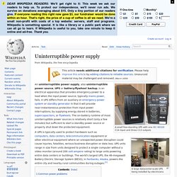
Future Challenges For Research And Teaching In Power Electronics. Uninterruptible power supply. A small free-standing UPS with one IEC 60320 C14 input and three C13 outputs A large datacenter-scale UPS being installed by electricians An uninterruptible power supply, also uninterruptible power source, UPS or battery/flywheel backup, is an electrical apparatus that provides emergency power to a load when the input power source, typically mains power, fails.
A UPS differs from an auxiliary or emergency power system or standby generator in that it will provide near-instantaneous protection from input power interruptions, by supplying energy stored in batteries, supercapacitors, or flywheels. The on-battery runtime of most uninterruptible power sources is relatively short (only a few minutes) but sufficient to start a standby power source or properly shut down the protected equipment.
Common power problems[edit] The primary role of any UPS is to provide short-term power when the input power source fails. Technologies[edit] Offline/Standby[edit] Offline/Standby UPS. Battery management system. A battery pack built together with a battery management system with an external communication data bus is a smart battery pack.
A smart battery pack must be charged by a smart battery charger. Functions[edit] Monitor[edit] A BMS may monitor the state of the battery as represented by various items, such as: Voltage: total voltage, voltages of individual cells, minimum and maximum cell voltage or voltage of periodic tapsTemperature: average temperature, coolant intake temperature, coolant output temperature, or temperatures of individual cellsState of charge (SOC) or depth of discharge (DOD): to indicate the charge level of the batteryState of health (SOH), a variously-defined measurement of the overall condition of the batteryCoolant flow: for air or fluid cooled batteriesCurrent: current in or out of the battery Electric Vehicle Systems: Energy Recovery[edit] Computation[edit] Additionally, a BMS may calculate values based on the above items, such as: Communication[edit] Serial communications.
Wireless Technology in the Smart Grid Space. Total harmonic distortion. In audio systems, lower THD means the components in a loudspeaker, amplifier or microphone or other equipment produce a more accurate reproduction by reducing harmonics added by electronics and audio media.
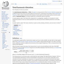
In power systems, lower THD means reduction in peak currents, heating, emissions, and core loss in motors.[1] Definitions[edit] To understand a system with an input and an output, such as an audio amplifier, we start with an ideal system where the transfer function is linear and time-invariant. When a signal passes through a non-ideal, non-linear device, additional content is added at the harmonics of the original frequencies. THD is a measurement of the extent of that distortion. When the input is a pure sine wave, the measurement is most commonly defined as the ratio of the RMS amplitude of a set of higher harmonic frequencies to the RMS amplitude of the first harmonic, or fundamental, frequency:[2][3][4][5][6][7][8] THD+N[edit] THD+N means total harmonic distortion plus noise. Bandwidth (signal processing) Baseband bandwidth.
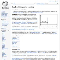
Here the bandwidth equals the upper frequency. Bandwidth is the difference between the upper and lower frequencies in a continuous set of frequencies. It is typically measured in hertz, and may sometimes refer to passband bandwidth, sometimes to baseband bandwidth, depending on context. Passband bandwidth is the difference between the upper and lower cutoff frequencies of, for example, a bandpass filter, a communication channel, or a signal spectrum. In case of a low-pass filter or baseband signal, the bandwidth is equal to its upper cutoff frequency. Harmonics. What Is Power Quality Webinar 9-12-2012. Intermodulation. A frequency spectrum plot showing intermodulation between two injected signals at 270 and 275 MHz (the large spikes).
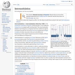
Visible intermodulation products are seen as small spurs at 280 MHz and 265 MHz. Intermodulation is caused by non-linear behaviour of the signal processing being used. The theoretical outcome of these non-linearities can be calculated by generating a Volterra series of the characteristic, while the usual approximation of those non-linearities is obtained by generating a Taylor series. Causes of intermodulation[edit] then the output is a signal which includes a number of integer multiples of the input frequency; (i.e. some of Intermodulation occurs when the input to a non-linear system is composed of two or more frequencies. , and ; which may be expressed as where the and are the amplitudes and phases of the three components, respectively.
We obtain our output signal, Www.aspowertechnologies.com/resources/pdf/Total Harmonic Distortion.pdf. Www.eng.tau.ac.il/~shmilo/10.pdf. Smart Grid, Utilities, and Internet Protocols.