
No More Splatter! "Splatter" on SSB transmissions is high-order intermodulation distortion (IMD) caused by gross overdriving on speech peaks.
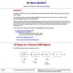
Any so-called "linear" amplifier will generate IMD if it is driven too hard. Your mission is to make sure that overdriving never happens - that's right, never! Speech processors are usually advertised as giving your signal more "punch" or "talk power". That can be true - but a speech processor can also help to eliminate splatter. If you adjust your speech processor correctly you can have a more "punchy" signal that gets the DX, and also a cleaner signal that doesn't offend local stations. Here's how to do it.
Clamp-on RF Current Meter. A clamp-on RF ammeter is not only useful for antenna experimenters but also as an aid to achieving good EMC in an amateur station.
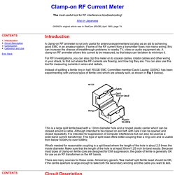
If some of the RF current from a transmitter flows into mains wiring, this can increase the chance of breakthrough problems in nearby TV, video or audio equipment etc. A clamp-on RF ammeter allows this current to be measured, so that steps can be taken to minimize it. For RFI investigations, you can also clip this meter on to coaxial cables, rotator cables and other wiring in your shack, to find out where the RF currents are flowing, and how big they are. You can also use this tool for measuring currents in wires and radials. Instead of splitting a ferrite ring in half, RSGB EMC Committee member David Lauder, G0SNO, has been experimenting with various types of ferrite core which are already split, as shown in Fig 1 (below). Building and calibrating a low capacitance RF current meter. It takes a special meter to measure current accurately in the presence of strong electric fields, and to not disturb low-capacitance high impedance systems.
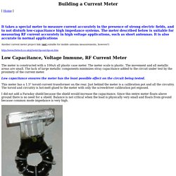
The meter described below is suitable for measuring RF current accurately in high voltage applications, such as short antennas. It is also accurate in normal applications. Meters. Alan Yates' Laboratory - Phantom-Powered Active Loop Receive Antenna for 30 Metres. This loop antenna was built for 30 metre QRSS reception, but tunes beyond 30 metres and might be useful for general narrow-band (fix-tuned) HF work.
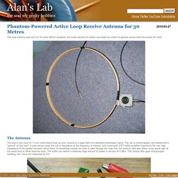
The Antenna The loop is two turns of ~3 mm multi-strand hook-up wire, wound on a large (465 mm diameter) embroidery frame. The coil is centre-tapped, and referenced to "ground" at that point. A polyvaricon tunes the coil to resonance at the frequency of interest, and a push-pull JFET buffer amplifier transforms the very high impedance of the parallel resonant circuit down to something suitable for what is seen through the coax from the receiver (and also offers some power gain at the same time to offset feed-line loss).
The buffer can deliver a relatively large amount of power, in excess of 0 dBm. Each J310 stands about 2.5 mA. More gain is available by bypassing the 100 Ohm source resistors. 'Multi-Four' VXO TX. 2 - Introduction I've had an interest in building a simple VXO transmitter for many years, but was unsure that the limited tuning range usually associated with VXOs would be useful on the busy HF bands.
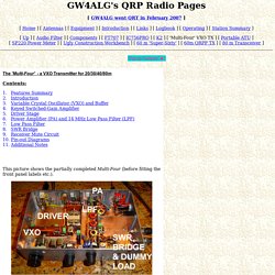
However, the ability to switch a number of crystals, and cover a number of different bands in one transmitter greatly increases the chance of finding a clear frequency on which to operate. Much of the design is based on the Super-Sixty 5 MHz QRP transmitter, described in the Winter 2002/3 issue of SPRAT (SPRAT Nr. 113). VK5AJL - Build your own micro-stripline SWR meter - the only way to measure SWR. The text of this project should be read in conjunction with STANDING WAVES in the info section.
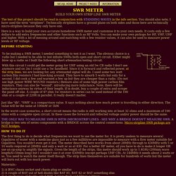
You should also note, I have used the term "striplines". Technically striplines have a ground plane on both sides and those here are technically micro-striplnes because they only have one. Here is a way to build your own accurate homebrew SWR meter and customise it to your own needs. It costs only a few dollars to add extra frequencies and other functions such as RF Volts. You can make your own pickups for HF, VHF, UHF and higher. VK5AJL - Build your own micro-stripline SWR meter - the only way to measure SWR. The text of this project should be read in conjunction with STANDING WAVES in the info section.

You should also note, I have used the term "striplines". Technically striplines have a ground plane on both sides and those here are technically micro-striplnes because they only have one. Here is a way to build your own accurate homebrew SWR meter and customise it to your own needs. It costs only a few dollars to add extra frequencies and other functions such as RF Volts. You can make your own pickups for HF, VHF, UHF and higher. SWR Bridge. Building Instructions: 1.
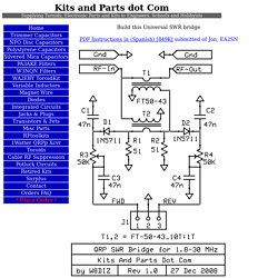
Inventory all Parts 2. Install all Resistors. PWR/SWR. Alan Yates' Laboratory - -20 dB Tap Attenuator. Another device I've been meaning to build for a long time.
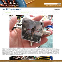
The QRSS work has caused more interest in attenuators and transmission line monitoring, my current bodgy attenuator was tested with my most recent instrumentation and found quite lacking - more work on that instrument soon... Pi or Tee pads have precision issues, especially if you only stock E12 resistor values, so this tap is based on a transformer, the familiar 10:1 turns ratio -20 dB tap. It can offer quite good accuracy if carefully constructed and terminated correctly on all ports. I tried various core materials and sizes. RC Low-pass Filter Design tool - Result - Chapter 3: PIC16F887 Microcontroller - Book: PIC Microcontrollers - Programming in C. Chapter 3: PIC16F887 Microcontroller The PIC16F887 is a well known product by Microchip.
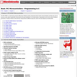
It features all the components which modern microcontrollers normally have. For its low price, wide range of application, high qual-ity and easy availability, it is an ideal solution in applications such as the control of different processes in industry, machine control devices, measurement of different values etc. Some of its main features are listed below. 256 bytes EEPROM memory Data can be written more than 1.000.000 times368 bytes RAM memoryA/D converter: 14-channels10-bit resolution3 independent timers/countersWatch-dog timerAnalogue comparator module with Two analogue comparatorsFixed voltage reference (0.6V)Programmable on-chip voltage referencePWM output steering controlEnhanced USART module Supports RS-485, RS-232 and LIN2.0Auto-Baud DetectMaster Synchronous Serial Port (MSSP) supports SPI and I2C mode Most pins of the PIC16F887 microcontroller are multi-functional as seen in figure above.
Embedded projects from around the web. Homebrew RF Test Equipment and Software. Low Cost Wireless Network How-To. Untitled. Return Loss Measurement kindly conducted and provided by Pierre Binggeli, HB9IAM Based on the Analog Devices AD8307AR chip, this module is a complete RF Power meter head for 50 ohm systems working from very low frequencies to more than 500 MHZ.
The RF input SMA is terminated to a 52.3 - 0.1% Ohms resistor (R1) to match the AD8307 input resistance to 50 Ohms. It draws under 12 mA at 12 VDC and has two internal voltage regulators. For low noise operation, a special ultra low-noise 3.3 V voltage regulator is used. On that route, two 100 nF capacitors are connected to the ground and can be removed or modified. Space for installing optional scaling resistors (R3 and R4 of 1206 size) is provided. Hf rf current detector. N4HAY / ZS6RSH. N4HAY / ZS6RSH: Gain Familiarity with Measurements in a 50 Ohm environment. N4HAY / ZS6RSH: RF Power Meter. Today I finished building my RF Power Meter. This is a design from EMRFD section 7 by W7ZOI. The schematic is self explanatory. It is basically 2 power meters in one. The meters read Peak RF voltage that is then converted to Power using the formula P = V^2/2R. I have completed the calibration of the bigger input using 15volts DC.
I need to get some bigger power resistors so that I can measure at least 5 watts. I performed a sweep using my antenna analyzer of both dummy loads. I am looking forward to calibrating the small meter which should allow me to measure down to about -8dBm. N4HAY / ZS6RSH: RF Power Measurements with a scope 50ohm terminator and attenuators. I wanted to measure the power output of my homebrew rig using a commercial scope terminator. The diagram of the two configurations is shown below. Because the terminator can only dissipate 1Watt maximum and to get some variation in readings, I used a set of calibrated attenuators of the following values 3dB, 6dB, 10dB and 20dB to reduce the input signal level from the TX into the scope load by a known amount.
I performed two sets of measurements 1) with the pad at the TX end of the coax and 2) with the pad at the terminator end of the coax. (see the diagram below). Thus the signal level into the scope was varied from +30dBm down to +13dBm. Examination of the two sets of results with different pads shows the following variations in mW. N4HAY / ZS6RSH: Testing the ZS6RSH Measurement Procedure. N4HAY / ZS6RSH: RF Power Meter Calibration reworked. I reworked the calibration procedures again for the 1N34A based power meter and the 1N4148 based power meters. The full calibration results are included on this Blog page. For the 1N34A I used a DC calibration procedure but this time I used my commercial attenuators to set the input DC Voltage levels. I then compared the measured voltages with the expected value. The correlation as can be seen from the table below is exactly the same. In other words the measured values = the expected values over the measurement range.
N4HAY / ZS6RSH: An RF Power Meter based on the Analog Devices AD8307 log/linear chip. On studying the RF Workbench series published on VE3BPO's brilliant website, QRP Homebuilder Todd, VE3BPO advises that an excellent 50Ohm RF workbench can be built inexpensively with a sensitive RF Power meter forming the core of the test environment. On RF Workbench page 5 VE3BPO outlines a list of basic tools needed to get started as an RF experimenter. Based on this I built a version of the Bare Bones RF Power Meter. I chose the Bare Bones version since I am currently only working on HF projects. I want to keep it simple. N4HAY / ZS6RSH: Calibrating the slope of the AD8307 Power meter. N4HAY / ZS6RSH: AD8307 Power Meter. The Analog Meter Calibration. In this procedure the aim was to adjust the current to voltage converter that drives the analog meter so that the meter would read about 75% of full scale deflection (FSD) at the maximum rated input of the power meter which is +15dBm.
N4HAY / ZS6RSH: Establishing the -10dBm point for the AD8307 Power Meter. I built the CMOS 10Mhz calibrator exactly according to the design published on the QRP Homebuilder website RF workshop page 5 found here under Part 2. N4HAY / ZS6RSH: Power Meter calibration using the Weinschel step & fixed attenuators. Now that I had established a few calibration points I wanted to establish further reference points. These would assist in determining the variances in linearity over the range -10dBm through -70dBm. N4HAY / ZS6RSH: Calibration of the AD8307 Power Meter using fixed attenuators. N4HAY / ZS6RSH: A sensitive Field Strength Meter. N4HAY / ZS6RSH: Understanding the RF Current sensor. I thought it might be instructive to set up a bench experiment to try to understand the performance of the RF Current sensor.
N4HAY / ZS6RSH: Understanding the RF Current sensor (2) Following from tests conducted and recorded in the previous blog I had to now compare the Z Match output with my Tank Circuit coupler that I have used for many years to feed a 40m end-fed. This was done using additional bench tests in the same manner as before. Stellaris® LM4F120 LaunchPad Evaluation Board Software - SW-EK-LM4F120XL. STM32CubeMX STM32Cube initialization code generator (UM1718) STM32CubeMX is part of STMicroelectronics STMCube™ original initiative to ease developers life by reducing development efforts, time and cost. STM32Cube covers STM32 portfolio. STM32Cube includes the STM32CubeMX which is a graphical software configuration tool that allows generating C initialization code using graphical wizards. Educating and Entertaining since 2003. Nintendo (NES) Electronic Circuit Schematic. Nintendo (NES) Schematic. ESP8266 WiFi relay switch (Arduino IDE) In this tutorial we will show how to build ESP8266 relay without Arduino in ESP8266 Arduino IDE.
ESP8266 Projects: PART3 - I2C Driver - MCP9808 - Temperature Logger - ESP8266 CBDB. EI9GQ homebrew radio page. N4SPP - directional coupler. Frank's N4SPP - RF-probe. Magnetizing Inrush Current in Power Transformer. Mini-Circuits : RF and Microwave Transformer Fundamentals : Article. SGC Smartuner with balanced dipole antenna. Devices : Analog Dialogue : transformer_vs_amp. LB3HC's hightech blog » Testing of a HF current transformer with a vector network analyzer. Analog Devices : Analog Dialogue : transformer_vs_amp. Low Phase Noise Design: Common Emitter Transformer Feedback Buffer Amplifiers.
The HF Current Probe: Theory and Application. Info: G3YNH info: G3YNH info: Current transformers. Part 2. G3YNH info: Current transformers. Part 1. RF Bridges. G3YNH info: Reflectometry. Things to build. A frequency counter circuit project written in C using TMR1 and an 8 digit seven. A PIC frequency counter project written in C using TMR1 and an LCD. Best Open Source Hardware. Textbook for Electrical Engineering & Electronics. ESP8266 Community Forum. $3 Wifi module part 10: A World Record?! Arduino TFT Forecast Weather Station with ESP8266. RF Communication Between Microcontrollers – Part I. RF Communication Between Microcontrollers – Part I. Electronic Circuits.
Video links for Embedded Systems. Getting Started with the TIVA™ C Series TM4C123G LaunchPad. SPICE Circuit Simulation. C# Programming. Free Samples. Electronic Circuits. Schematic Capture. AVR Microcontroller. ARM Microcontroller. PIC Microcontroller. Pipes. Process Flow. Arduino. Raspberry PI. Électronique. ESP. Arduino/Raspberry Pi.