
アナログ電子楽器の回路を読む. Eg0104a. 16 Step Sequencer Using CD4017s: アナログ電子楽器の回路を読む. Unusual synth circuits. I built original modular synths when I was a high school student.
Rate 1990’s, I joined synth-diymailing list and resumed synth DIY. I'm not good at English but I am trying to write most ofthe contents in English for the list members who have inspired me. US4604532A - Temperature compensated logarithmic circuit. This application is a continuation of application Ser.
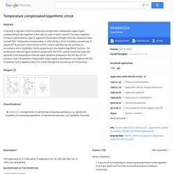
No. 455,240, filed Jan. 3, 1983, now abandoned. 1. Field of the Invention This invention relates to electrical circuits for producing output signals according to a logarithmic function. More particularly, this invention relates to improved circuitry for developing a temperature-independent logarithmic output signal. Corporation: How to Build a 2 Note Ribbon Controller by John Simonton. By John Simonton Even if you've never played with a ribbon controller you have at least seen one and know what they are.
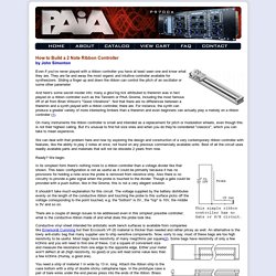
They are far and away the most organic and intuitive controller available for synthesizers. Sliding a finger up and down the ribbon can control the pitch of an oscillator or some other parameter. AMZ Warp Controls. One little used effects technique is the “warp control”.
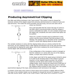
This control is used to change the harmonic content of the clipped output from primarily odd harmonics to a mixture of even and odd harmonics. This makes the sound smoother and less buzzy, and can even add a bit of octave-up character. One could speculate that the reason this type of control is not often used in commercial boxes is that the change in sound is noticeable but subtle. It is not a drastic enough that the added cost, complexity and extra control knob space can be justified. There are a variety of simple ways to implement a warp control, and the sound character that they produce is not identical. AMZ Saturation Controls and Diode Clipping. When the pot adjustment is to the left, there is less resistance and the clipping is more harsh than when adjusted to the right.
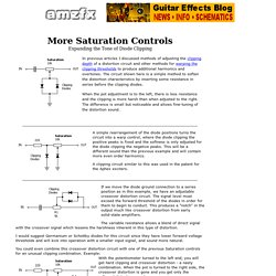
The difference is small but noticeable and allows fine-tuning of the distortion sound. A simple rearrangement of the diode positions turns the circuit into a warp control, where the diode clipping the positive peaks is fixed and the softness is only adjusted for the diode clipping the negative peaks. This will be a different sound than the previous example and will contain more even order harmonics. Synthesizer DIY resources www.haraldswerk.de. Schematics Vault. The Voltage Controlled Quadrature Function Generator Project by Thomas Henry ,page dedicated to this module is at Birth of a Synth by Scott Stites visit for details on construction , calibration procedure and more .From there the brief description : Through the years, Thomas Henry has designed a lot of synthesizer circuits - you name it, he's designed at least one version of it - VCOs, envelope generators, VCAs, filters, sequencers, flangers, phase shifters, drum voices...pretty much the gamut of things that make our synthesizers tick.
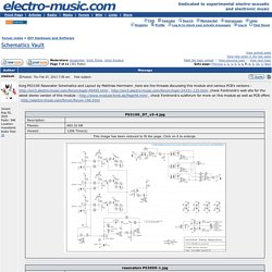
Schematics / Moog Parametric Equalizer. DIY | Filter | Fixed Filter | Equalizer | Parametric | Moog | ACX Synth Moog Parametric Equalizer by ACX Synth ,visit for more information and details on this Moog adaptation and various other modules as well as pcb offers .
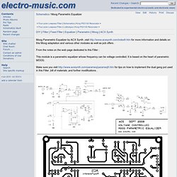
From the notes on the web page dedicated to this Filter : This module is a parametric equalizer whose frequency can be voltage controlled. It is based on the heart of parametric MOOG. Make sure you visit for tips on how to implement the dual gang pot used in this Filter ,bill of materials ,and further modifications . Tim Stinchcombe - Serge VCS & how it works. Serge VCS - How it Works This page focuses on the Serge VCS voltage-controlled slope circuit, as embodied in the Cat Girl Synth CGS75 module (available as a PCB), and the Bananalogue Serge VCS module.
(It appears that the Bananalogue website, www.bananalogue.com, disappeared sometime in 2008, but the VCS page (including the pictures) is viewable at the Internet Archive, and as of December 2009 the module has once again been made available through Big City Music.) LINEAR SWEEP GENERATOR. Mickeymouselogic. CMOS Mickey Mouse Logic Article by Ray Wilson Understanding Mickey Mouse Logic (MML)
Schematics / Schematics. SchematicsListbytype A collection of synth related schematics, collected by vladosh on the forum and copied to here by Blue Hell and vladosh.
There is an automatically maintained sorted index here. You can search the Vault through the search box above by using a search expression preceded by Schematics/ e.g Schematics/lfo to search for LFO's. Note on Copyright: electro-music.com always respected the great amount of work, effort and time invested by individuals in making a better synthesizer ,better designs . Electronotes. Low-cost-voltage-to-frequency-converter_Circuit Diagram World. Declaration:We aim to transmit more information by carrying articles . We will delete it soon, if we are involved in the problems of article content ,copyright or other problems. The 741 op amp integrator signal is fed into the Schmitt trigger input of an inverter. When the signal reaches the magnitude of the positive-going threshold voltage, the output of the inverter is switched to zero. The inverter output controls the FET switch directly. Circuit Diagram World.
Art's Theremin Page: Transposable Chord Generator. Transposable Chord Generator This circuit consists of three precise triangle-wave oscillators, each using an Analog Devices type AD654 voltage controlled oscillator (VCO) and an AD620 instrumentation amplifier (INAMP). Art's Theremin Page: Symmetrical Digital Dividers. Symmetrical Digital Dividers These digital divider circuits permit the division of a frequency by odd integers (three, five and seven illustrated) while maintaining an output with a nearly-perfect 50% duty cycle square wave.
This symmetry is useful in music applications where square waves may be filtered efficiently to extract the fundamental sine wave, with, for example, switched capacitor or continuous low-pass filters. The first example's waveforms (divide by three) illustrates the basic technique of deriving appropriate positive-edge clocking transitions by utilizing an exclusive-or gate preceding the first flip-flop (U1A). The very-short transitions at the output of U1A correspond to the time of propagation through the two flip-flops and the gate. A supply of +5 volts is indicated, although the CMOS devices shown operate within a range of +3 to +15 volts. December 11, 2012. Art's Theremin Page: Four Phase Clock Generator. Four Phase Clock Generator Here is an extremely useful circuit that may be applied as the timing core for any sequential digital process, using a single dual-flip-flop package, CMOS type CD4013BE.
One of the four outputs (phase 1) provides a squarewave at one-quarter the clock input frequency. The phase 2 output provides a squarewave one clock cycle later, and phases 3 and 4 follow with a delay of two and three clock cycles, respectively. A supply of +5 volts is indicated, although the CD4013BE device may operate within a range of +3 to +15 volts. The maximum recommended clock rate is 3.5MHz for a +5 volt supply.
My gratitude to Rick Hansen, who introduced me to this circuit and the essential tenets of digital logic in the 1980s. November 30, 2012 Text and image ©2012 by Arthur Harrison. Art's Theremin Page: Square Wave to Triangle Wave Converter. This circuit converts a square waveform to a triangle waveform while automatically maintaining a constant triangle amplitude for a wide range of input frequencies. Although originally designed for application in a communications system, the idea is readily adaptable for certain electronic music applications where waveform conversion is desired. Operation is as follows: Transistor Q2 provides a square wave at its collector that has an amplitude controlled by Q1.
The square wave is fed to an integrator consisting of operational amplifier U1A and associated components. Operational amplifier U1B integrates U1A's output, compares it to ground, and provides a term at U1A's positive input that maintains U1A's output centered about ground. Operational amplifiers U2A and U2B and associated components comprise a full-wave precision rectifier and averaging circuit. Dintree - Synth DIY. How to Produce 18 Sequential Outputs by Cascading 4017 IC - Light Chaser Circuit. Circuit Description. Tim Stinchcombe - Serge VCS & how it works. AMZ Warp Controls. Pucktronix / usb-octomod. The USB-Octomod is a USB device which allows generation of computer-controlled analog synthesizer control voltages in the range of approximately +/- 5V.
Software / Circuitry. A Homemade Variable Tuning Capacitor for tuning in your FM stations... Get loopy with the DIY $10 Ableton Footcontroller (no soldering required) Schematics / Moog Parametric Equalizer. Index of -diy-Schematics.url. Darrenyates.com.au/electronics. ECE4893A: Electronics for Music Synthesis (Spring 2010) Office: Centergy 5212 (but I'm almost never there) Phone: 404-385-2548 (but I almost never answer it) E-mail: lanterma@ece.gatech.edu (by far the best way to reach me; please include "EMS" somewhere in the subject of class-related e-mail so I can find it quickly)Course website: users.ece.gatech.edu/~lanterma/ems10 Prerequisites: ECE3040 and ECE3041 (with concurrency allowed, i.e. you can be taking ECE3041 this semester and be OK).
Basically, I need some familiarity with op amps, diodes, and transistors, and I need to make sure that you have had some experience using a scope by the time you will to use one in EMS. AES1.PDF. Larry’s DIY synthesizer module page. Download mp3 page. Unusual synth circuits. Juergen Haible. Antonelli_2375_Organ_Schematics_XA. Experimentalists Anonymous - Archives. CMOS Synthesizers. Chip Basics. Op_amp_circuit%20collection_AN-31. Fun with sea moss (or, basic digital sound devices) By Sebastian Tomczak. Please email stomczak@e-access.com.au for blah-blahing.
Free Simple Circuit Diagram.