
555 Timer Circuits. We share technology insights and DIY ideas. Diy4fun. Geeksinside.com. Learning Electronics : Free Electric Circuits Textbooks. Electronic Circuits Diagrams-Electronics Projects Designs-Hobby Circuits. Electronics Lab - Open Source Hardware Electronic Projects. Explore Electronic Circuits and Tutorials - Discover Engineering Hobby Projects - Computer Based Microcontroller Projects - Science Experiment Videos. Electronic Circuits, Electronics Design, Hobby kits, Projects. Electronics tutorials for newcomers learn basic electronics for free. Electronic Circuits - Free Electronic Circuits. All About Circuits : Free Electric Circuits Textbooks.
Complete List Of Electronics Projects Circuit Diagram. How to Make a Simple Stereo Audio Amplifier Circuit Using IC 1521. A simple stereo audio amplifier circuit discussed here is built around the IC TDA 1521, requires very few external passive components and is able to provide a powerful 12 + 12 watts of music output.

The IC contains all the built in features required for an amplifier circuit like automatic mute, overload and over heat protections. The circuit of a stereo audio amplifier using IC TDA 1521 presented here is very simple to build, utilizes very few external components and yet is able to produce 12 + 12 watts of hi-fi music power. The input can be from a CD player or your cell phone Building a stereo audio amplifier usually refers to using two mono amplifiers and integrating their inputs, common ground and the supply to get the required stereo provisions. However such circuits generally tend to become too bulky and moreover making identical modules simply makes everything double and thus the costs involved also get doubled.
The chip carries a special in-built music mute facility. TIDesigns. A Robust Glass-Breakage Detector Reference Design This reference design describes a simple as well as a robust glass breakage detector designs using the and was developed to operate at low power, allowing long battery life.

The simple design algorithm is based on the spectral analysis of a typical glass breakage signal by analyzing signal characteristics such as peak content, number of zero crossings, and frequency composition. Does Volts or Amps Kill You? Voltage, Current and Resistance. Electronic Resources - A to Z - A-Z Electronic Resources - Library Guides at Berea College. Category:Electronic albums. Making the world a better place, one Evil Mad Scientist at a time. Battery-Less 6LoWPAN-Based Wireless Home Automation by Use of Energy Harvesting. Transceiver. Radio technology[edit]
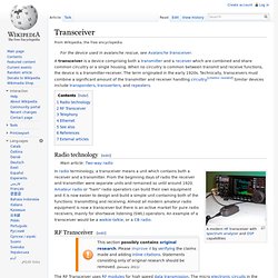
Electrical Engineering Stack Exchange. Electronic Resources - A to Z - A-Z Electronic Resources - Library Guides at Berea College. Oscilloscope usb. EMF Detector DT-1130.
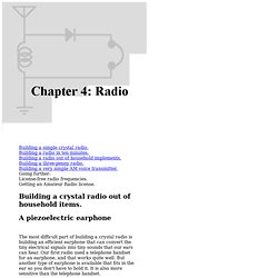
E news. WikiProject Energy. Chapter 4: Radio. Send mail to Simon Quellen Field via sfield@scitoys.com.
Category:B-Class electronic articles. WikiProject Electronics. WikiProject Electronics/Standard symbols. Reference should be made to codes and standards. eg IEC 60027, Letter Symbols in Electrical Technology Here are tables of widely accepted symbols.
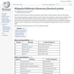
They are meant to be a guideline: using the same symbols for the same things in different articles will increase their consistency, making them easier to understand and to improve. If you are looking for the symbol for something that is not on the list, just check whether a particular symbol has been already chosen, and create your own. If anybody will disagree with it, discuss it on the talk page.
It is certainly not an exhaustive list, nor is it in any particular order. Computer & Tech Dictionary - the high-tech computer dictionary.
IEEE eLearning Library. Microwave. Radio. IEEE eLearning Library. Components. Electronic component. Various electronic components An electronic component is any basic discrete device or physical entity in an electronic system used to affect electrons or their associated fields.
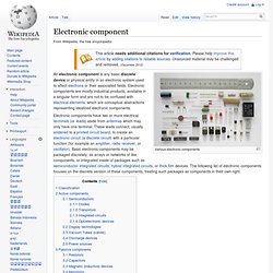
Electronic components are mostly industrial products, available in a singular form and are not to be confused with electrical elements, which are conceptual abstractions representing idealized electronic components. Classification[edit] Active components rely on a source of energy (usually from the DC circuit, which we have chosen to ignore) and usually can inject power into a circuit, though this is not part of the definition.[1] Active components include amplifying components such as transistors, triode vacuum tubes (valves), and tunnel diodes.Passive components can't introduce net energy into the circuit. They also can't rely on a source of power, except for what is available from the (AC) circuit they are connected to. A Rough Guide to Electronics - Lesson 3. Capacitors are stores for electrical charges.

Resistor. Axial-lead resistors on tape.
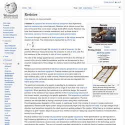
The tape is removed during assembly before the leads are formed and the part is inserted into the board. In automated assembly the leads are cut and formed. The current through a resistor is in direct proportion to the voltage across the resistor's terminals. This relationship is represented by Ohm's law: TEARA's "KnowledgeQuest" - A Technical Article about Resistors. By Lynwood Hobbs AF4XJ WAIT!!
If you came to this page directly from a search engine or link, you're missing out on hundreds of pages of amateur related info on our site. CLICK HERE, or click the floating TEARA link on the page, to move to the top of our site. From there, you can select 'KnowledgeQuest', and return to this page, complete with all of our site navigation tools. Circuit diagram. Comparison of pictorial and schematic styles of circuit diagrams Common schematic diagram symbols (US symbols) Unlike a block diagram or layout diagram, a circuit diagram shows the actual wire connections being used.
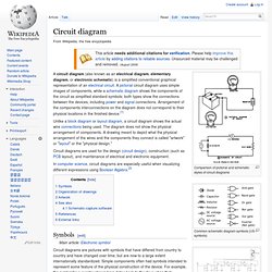
The diagram does not show the physical arrangement of components. A drawing meant to depict what the physical arrangement of the wires and the components they connect is called "artwork" or "layout" or the "physical design. " Circuit diagrams are used for the design (circuit design), construction (such as PCB layout), and maintenance of electrical and electronic equipment. In computer science, circuit diagrams are especially useful when visualizing different expressions using Boolean Algebra.[2] Symbols[edit] Schematic wire junctions: 1. The linkages between leads were once simple crossings of lines; one wire insulated from and "jumping over" another was indicated by it making a little semicircle over the other line. Ohm's law. V, I, and R, the parameters of Ohm's law. where I is the current through the conductor in units of amperes, V is the potential difference measured across the conductor in units of volts, and R is the resistance of the conductor in units of ohms.
More specifically, Ohm's law states that the R in this relation is constant, independent of the current.[3] The law was named after the German physicist Georg Ohm, who, in a treatise published in 1827, described measurements of applied voltage and current through simple electrical circuits containing various lengths of wire. Search Results.