
Keplers Second Law Interactive. List of paradoxes. This is a list of paradoxes, grouped thematically.
The grouping is approximate, as paradoxes may fit into more than one category. Because of varying definitions of the term paradox, some of the following are not considered to be paradoxes by everyone. This list collects only scenarios that have been called a paradox by at least one source and have their own article. Although considered paradoxes, some of these are based on fallacious reasoning, or incomplete/faulty analysis. Informally, the term is often used to describe a counter-intuitive result. Logic[edit] Self-reference[edit] These paradoxes have in common a contradiction arising from self-reference.
Barber paradox: A barber (who is a man) shaves all and only those men who do not shave themselves. Vagueness[edit] Schoolphysics. Daniel McClelland Presentations. Physics Flash Animations. We have been increasingly using Flash animations for illustrating Physics content. This page provides access to those animations which may be of general interest. The animations will appear in a separate window. The animations are sorted by category, and the file size of each animation is included in the listing. Also included is the minimum version of the Flash player that is required; the player is available free from The categories are: In addition, I have prepared a small tutorial in using Flash to do Physics animations.
LInks to versions of these animations in other languages, other links, and license information appear towards the bottom of this page. Physics 1 for OCR Cambridge OCR Advanced Sciences: Amazon.co.uk: David Sang, Gurinder Chadha. Physics. Biscuit Tin Alarm#PCB#PCB#PCB#PCB#PCB#PCB#PCB#PCB#PCB#PCB#PCB#PCB#PCB#PCB#PCB#PCB#PCB#PCB#PCB#PCB#PCB. Biscuit Tin Alarm Project Someone is stealing the biscuits!
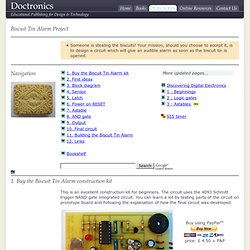
Your mission, should you choose to accept it, is to design a circuit which will give an audible alarm as soon as the biscuit tin is opened. Navigation Custom Search 1. This is an excellent construction kit for beginners. DOCTRONICS accepts official orders from UK educational establishments. Click if you want to build the circuit now. 2. If you haven't designed a circuit before, the mission may seem impossible, but the process of electronic design is not really difficult.
Ask questions: How are you going to detect when the biscuit tin is opened? A light dependent resistor, LDR, could be used as part of a light sensor circuit. Most alarms 'remember' that the sensor subsystem has been triggered. Once you know the names and properties of the most important subsystems, you can use these building blocks to work out how to solve the design problem in outline. Flashing LED unit - Electronic Circuits and Diagram-Electronics Projects and Design.
Description. The circuit given here is designed as an LED flasher which produces a rotating effect when the LEDs are arranged properly. The circuit has very low current consumption and can be operated from even 3V button cells. The IC 1 (CMOS NE555) is wired as an astable multivibrator wired at a duty cycle of 50% and 4Hz frequency and drives LEDs D1 to D6.The second IC, IC2 (CMOS NE555) is working as a trigger pulse inverter and drives LEDs D7 to D12.The circuit is arranged such that the ICs sink the current consumed by the LEDs.
At low operating voltages like 3V, the CMOS NE 555 performs better when arranged in sinking mode rather than in sourcing mode. Simple LED flasher circuits. By simple, I mean that these circuits only flash one or two LEDs. This is opposed to the light chaser circuits that can flash four or more. Of course, the simplest LED flasher is simply to use a flashing LED. The problem with that approach is you have no control over the flash rate, but it does have its use for eye catching displays for selling stuff. The circuits below give you that control, plus they can flash two LEDs alternately. There are many possible applications for the circuits below, especially for kids, who love flashing lights.
Railroad crossing signal for model railroads. Transistor LED flasher This circuit has a lot going for it. On this circuit, the green wires connect to the LEDs, but you can mount them on the actual circuit board for some applications. Basic LED flasher circuit using NE555 timer IC This circuit consumes more power, but it's advantage is when you need a variable flash rate, like for strobe circuits. LM3909 LED flasher chip. Electric circuit builder. Breadboard. Electronic color code. RMA (Radio Manufacturers Association) Resistor Color Code Guide, c. 1945-1955.
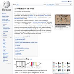
The electronic color code is used to indicate the values or ratings of electronic components, very commonly for resistors, but also for capacitors, inductors, and others. A separate code, the 25-pair color code, is used to identify wires in some telecommunications cables. The electronic color code was developed in the early 1920s by the Radio Manufacturers Association (now part of Electronic Industries Alliance[1] (EIA)), and was published as EIA-RS-279.
The current international standard is IEC 60062.[2] Colorbands were commonly used (especially on resistors) because they were easily printed on tiny components, decreasing construction costs. Resistor color-coding[edit] One decade of the E12 series (there are twelve preferred values per decade of values) shown with their electronic color codes on resistors A 100 kΩ, 5% axial-lead resistor. Colour coding of resistors. Module 1: Electric Current.