
The Offshoring of Engineering: Facts, Unknowns, and Potential Implications - Committee on the Offshoring of Engineering. The Water Treatment Process. The Water Treatment Process Click Titles to skip to: Chemical Process, Coagulation Chemistry, Clarification, Following Clarification Filtration Disinfection Notice to Fish Owners and Dialysis Patients Overview The majority of water supplied to Project 7 for treatment comes from the Blue Mesa Reservoir via the Crystal Reservoir.
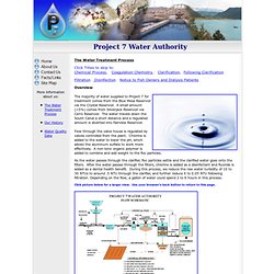
A small amount (<5%) comes from Silverjack Reservoir via Cerro Reservoir. Flow through the valve house is regulated by valves controlled from the plant. As the water passes through the clarifier, floc particles settle and the clarified water goes onto the filters. Click picture below for a larger view. Chemical Process Top of Page The materials we are attempting to remove in this process are particles of varying size and differing properties.
Fortunately, algae are not a significant issue for Project 7 as it can be in some operations. Why do I care about phase diagrams? In facilities operations the understanding of where the process is on a phase diagram can often help the engineer and operator avoid extremely embarrassing design and operating mistakes.
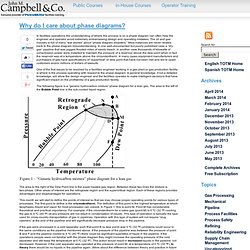
The oil and gas industry is full of many “war stories” about “phase diagram disasters.” Most instances are never related back to the phase diagram misunderstanding. In one well-documented but poorly published case a “dry gas” pipeline that was pigged flooded miles of sandy beach. In another case thousands of kilowatts of compression power were installed to maintain the pressure of a reservoir above the dew point when in fact the reservoir was at a temperature above the cricondentherm. In many cases equipment manufacturers and purchasers of gas have specifications of “superheat” or dew point that have not been met and led to upset customers and/or millions of dollars of lawsuits.
The following figure is a “generic hydrocarbon mixture” phase diagram for a lean gas. Control and Instrumentation. Plant Safety & SIS - Trips & Interlocks. Trips and Interlock Systems Protective tripping systems provide a defense against excursions beyond the safe operating limits by detecting an excursion beyond set points related to the safe operating limits (i.e. the onset of a hazard) and taking timely action to maintain or restore the equipment under control to a safe state.
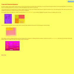
A trip system may be very straight forward, involving a simple actuation of a final control element when the sensor detected a deviation from a safe operating limit. Often, the trip system is more complicated, with interlocks sequence involving several pieces of equipment. An example is shown in the Figure for a Heater interlock system. An "interlock table" is also provided to highlight the possible causes and resulting action of a trip. A more informative interlocks cause-and-effect table as shown provides additional information on the instruments and trip settings. Back on Top.
INSTR & CONTROLS. Schematic Symbols Chart (Design Hydraulic and Pneumatic circuits/diagrams) Other Technologies content from Hydraulics and Pneumatics. To control the speed of an actuator, most designers use flow controls.
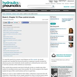
Air circuits normally need controlled flow because the plant air compressor is greatly oversized for almost any given circuit. Hydraulic circuits usually have a dedicated power source sized to meet the cycle time so flow restrictors are unnecessary. Flow controls always generate some heat in hydraulic circuits, so consider some other method of controlling actuator speed where possible. The circuit examples in this chapter explain the types of flow-control systems and how to apply them. Figures 10-1 and 10-2 show symbols for fixed orifices, rudimentary components that will control flow. Use the needle valve shown in Figure 10-3 when control of fluid flow in both directions is necessary. When talking about flow-control hardware, some manufacturers use different terminology. Hydraulics and Pneumatics Home Page. IEA Bioenergy Task Force. eBooks content from Hydraulics and Pneumatics.
Principles of Hydraulics. 5-2.
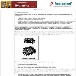
Directional-Control Valves Directional-control valves also control flow direction. However, they vary considerably in physical characteristics and operation. The valves may be a- Poppet type, in which a piston or ball moves on and off a seat. Directional-control valves may also be classified according to the method used to actuate the valve element. Directional-control valves may also be classified according to the number of positions of the valve elements or the total number of flow paths provided in the extreme position. Spool valves (see Figure 5-11) are popular on modern hydraulic systems because they- Can be precision-ground for fine-oil metering.
Spool valves, however, require good maintenance. FREE STUDY.