
LED dotmatrix sign ATtiny2313. On this page you will find a scrolling LED sign based on the ATtiny2313 AVR microcontroller, which you can build yourself (when finished) Other names for this device can be: Moving message sign, Message crawler, Scrolling message, message display, etc.The idea is to let a text scroll over the LED dot-matrix displays.
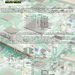
A dot-matrix display is a display which contains 5x7 dots (LEDs) in one case, the LEDs are connected like a matrix, there are two types CC and CA, the LEDs are simply put the other way around, here the drawings (inside and front): The 74HC595 is an 8-bit shift-register IC, with this IC you can shift 8 bits to the outputs with only 3 wires, that are Data (Ds), and 2 shift inputs (SHcp, STcp), connect like the diagram.
Lab 12: Basics of LED dot matrix display. We covered how to interface seven segment LED displays to a PIC microcontroller in two sections: Lab 6 and Lab 11.
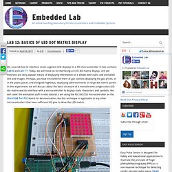
Today, we will move on to interfacing an LED dot matrix display. LED dot matrices are very popular means of displaying information as it allows both static and animated text and images. Perhaps, you have encountered them at gas stations displaying the gas prices, or in the public places and alongside highways, displaying advertisements on large dot matrix panels. Lab 15: Scrolling text message on an LED dot-matrix display. In Lab 12, we learned about the basic structure of a monochrome (single color) LED dot matrix and its interface with a microcontroller to display static characters and symbols.
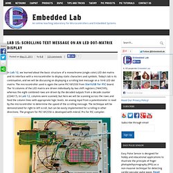
Today’s lab is its continuation, and we will be discussing on displaying a scrolling text message on a 16×8 LED dot matrix. The microcontroller used is again the same PIC18F2550 from StartUSB for PIC board. The 16 columns of the LED matrix are driven individually by two shift registers (74HC595), whereas the eight combined rows are driven by the decoded outputs from a decade counter (CD4017).
In Lab 12, columns were scanned, but here we will be scanning across the rows and feed the column lines with appropriate logic levels. An analog input from a potentiometer is read by the microcontroller to determine the speed of the scrolling message.