
Homemade Circuit Designs Just for You: How to Make 1 A Constant Current LED Driver Circuit. The article explains a simple circuit using the IC MBI6651 from MACROBLOCK.

The IC has been specifically designed for operating high power LEDs safely by providing a constant current output. The circuit includes very few external components and therefore becomes very easy to assemble at home.About the IC MBI6651 The IC MBI6651 is a high efficiency, step down DC to DC converter chip capable of driving high power LEDs at a safe 1 Amp constant current. The IC requires just four passive external components for making it functional. The output current of the IC can be externally set by selecting the appropriate resistor value. Typical Application of this device are: Automotive decoration and illumination LED flood lights using high intensity, high power LED. Setting the output Current The output current of the IC is fixed through an external resistor Rsen. Optimizing External Component Selection Inductor: Two issues specify the inductor type, the switching frequency and the ripple current.
AN4105.pdf (application/pdf-Objekt) Electronics Forum -> Led Drivers. I often saw people asking about how to drive LEDs so I thought I would put together a small collection of LED drivers I have tried. the simplest LED driver is a linear LED driver.
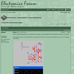
It is usually done with a BJT as a switch and controlled by a mcu (3.3v to 5v typical), as see below. two design considerations: 1) the current drain on the mcu: most MCUs can output 2ma from their GPIO pins, some can go as high as possible. LEDs are typically around 20 - 30ma with some much higher (350-700ma for example). so you want to make sure that when the mcu goes high, the switcher doesn't drain too much current out of the mcu. the current drain out of the MCU is limited by the base resistor R2. Vin=Iin*R2+Vbe, where Vbe is the voltage drop off the b-e junction of the switcher, typically 0.7v for a singleton, 1.3v for a darlington, and around 2v for a logic level mosfet (4v for a regular mosfet). Vcc=If*R1+Vf+Vce(sat). Vf needs to be checked out of your LED's datasheet, usually 2v - 3.5v. Constant current LED driver circuits. Roundup: Driving, dimming, and protecting LEDs – A list of DIY circuits and articles for LED power and control.

An LED constant current source (PDF) – This simple design drives LEDs in a series/parallel arrangement. The circuit uses an LM317L plus a transistor on each parallel string to prevent current-overload if one parallel string fails open. Why drive white LEDs with constant current? – Includes a good background that discusses different ways of powering LEDs and the advantages of constant current sources. Constant current LED driver circuit uses LM334 plus one transistor to drive a series string of LEDs. This constant current source design on Instructables.com uses a two-transistor design to power a series string of LEDs. Here’s another constant current driver schematic using two transistors. This is a constant current LED driver design that delivers high current (200 mA). This IC plus a capacitor and resistor (PDF) provides a constant current drive for up to four strings of LEDs. Constant current source with LM317. LED-Konstantstromquelle. [Willkommen] [Kontakt] [Archiv] [Lesezeichen] Allgemeines Leuchtdioden (kurz: LEDs) werden zunehmend auch für Beleuchtungszwecke eingesetzt.
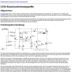
Im Gegensatz zu Glühlampen werden LEDs nicht an einer konstanten Spannung sondern mit einem konstanten Strom betrieben, was ein entsprechendes Vorschaltgerät in Form einer Konstantstromquelle erfordert. Im folgenden wird eine LED-Konstantstromquelle beschrieben, die aufgrund des verwendeten Schaltreglerprinzips gerade bei Hochleistungs-LEDs besonders effizient ist.
Die Stromquelle arbeitet als Abwärtswandler. Schaltungsbeschreibung Die Konstantstromquelle besteht im wesentlichen aus einem Abwärtswandler, dessen Strom durch einen Zweipunktregler geregelt wird. Wird der Transistor T6 eingeschaltet, so fließt ein Strom durch R3, die LEDs, die Spule L1 und den Transistor T6. Die Spannung über dem Widerstand R3 wird durch den Doppeltransistor T1/T2 verstärkt. Der Strom durch die LEDs ergibt sich näherungsweise zu 17 mV / R3. Simulation Aufbau.