
10 x MP2307 3A DC to DC Step-down Power Module KIS-3R33S - Free Shipping. Gmail: Email from Google. LED calculator for single LEDs. MC34063A design tool. Direct Power! Why not just connect your battery straight to the LED?
It seems so simple! What's the problem? Can I ever do it? The problem is reliability, consistency & robustness. As mentioned, the current through an LED is very sensitive to small changes in the voltage across the LED, and also to the ambient temperature of the LED, and also to the manufacturing variances of the LED. Inductor Designer / Calculator. Arduino mood light. I recently saw the cool mood lamp by Philips and I liked it.

What I did not like was the price. I set myself to discover what the industry has to offer in terms of high-power LEDs. It turns out that since the old 20mA red LEDs the market has evolved in such a way that it seems the light appliances of the future might be completely LED-powered. Now there are 3W and 10W LEDs available. Either monochrome or RGB.
Open Hardware MoodLamp « « DanielAndrade.net DanielAndrade.net. Long time ago I came across this page where Toon Beerten created a Moodlamp using a PIC16F628 µC.
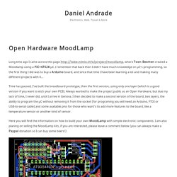
I remember that back then I didn’t have much knowledge on µC’s programming, so the first thing I did was to buy a Arduino board, and since that time I have been learning a lot and making many different projects with it… Time has passed, I’ve built the breadboard prototype, then the first version, using only one layer (which is a good version if you want to etch your own PCB). Always wanted to make the project public as an Open Hardware, but due my lack of time, I never did, until I arrive in Genova. Blog Archive » Arduino-controlled IKEA Lamp. Posted by adminon September 07, 2009Arduino, Projects This is a project I have been working on for the past 2-3 weeks. I wanted to create a night light which had to be very simple to use and with no parts that can be consumed by babies! I used 20 RGB LEDs (which I got from www.oomlout.co.uk), an old Eriksson phone charger and, of course an arduino board (actually I used an old SparkFun clone).
And a push button… And an Ikea lamp (”Lampan”, currently priced at £2.59 in the UK, around $5 in the States, This is a very cheap lamp, very hackable and safe for kids too (as all the components are safely hidden away). Many projects are based around this lamp: I found that the old Eriksson charger delivers approx 6V, which is good enough for the Arduino. I did the same on the IKEA lamp – I added 9V clips on both sides of the cable. I fitted the 20 LEDs on one board. Here is the final lamp: Arduino-powered IKEA Lampan Lamp from Arkadian.Eu on Vimeo. Schematic of 8x8 Led Dot Matrix Clock using PIC16F627A.
The above schematic is 8x8 Led Dot Matrix clock using PIC16F627A (or PIC16F628 which is more expensive but larger memory) and a shift register 74HC595.

The PIC is running with 4MHz internal oscillator so pin 15 (RA6) and 16 (RA7) are free. Therefore, the PIC16F627a can drive the 8x8 Led Drive matrix with these 2 free pins (RA6, RA7) and RB0-5, . The Timer1 (TMR1) external clock is generated by the watch crystal 32.768KHz + load capacitors 15pF and fed to RB6 and RB7. The pins are used up!. Put It to Use! 8x8 Matrix Mapping (hex,binary) Looking for: Easy to build LED driver Howto / Schematic. LEDs, 555s, PWM, Flashers, and Light Chasers Index. LEDs, 555s, PWM, Flashers, and Light Chasers by Bill Marsden, courtesy of I'm moving this article to blog format to allow me greater flexability in editing.

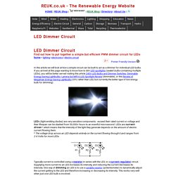
Please, do not comment in the blog, if you do I will delete it. If you want to leave a comment do it here. If you want to copy this for any use feel free, but please leave my name and the forum attached. One of the most common requests at All About Circuits is various methods of flashing LEDs. Index 1....LEDs 2....Current Limiting 3....The LED / Resistor Only Bargraph 4....The 555 Integrated Circuit 5....The 555 and PWM 6....Low Power Applications 7....The Joule Thief 8....From Four, Twenty 9....Light Chasers 10.l.Transistor Drivers.......BJTs.......MOSFETs 11.l.Making Patterns 12...Special Effects........Throbbing LEDs........Fading LEDs........Flickering LEDs (Fire!)........ LED Dimmer Circuit - Lighting. Find out how to put together a simple but efficient PWM dimmer circuit for LEDs home > lighting | electronics | electric circuitIn this article we will look at how a simple circuit can be built to act as a dimmer for individual LED bulbs.
Highly Efficient 0-100% LED Dimmer. This webpage describes a highly efficient LED dimmer, or a dimmable LED flashlight, or a switching current source, or whatever you want to call it.
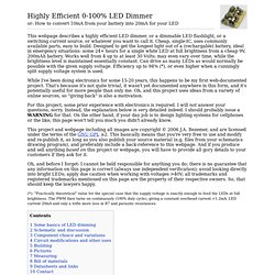
Cheap, single-IC, uses commonly available parts, easy to build. Designed to get the longest light out of a (rechargable) battery, ideal in emergency situations: some 24+ hours for a single white LED at full brightness from a cheap 9V, 200mAh battery. Works well from 4 up to at least 30 Volts; may even vary over time, while the brightness level is maintained essentially constant. Can drive as many LEDs as would normally be possible with the given supply voltage.