Arduino
> Shailu178
DHT11 Library for ARDUINO (UNO)
Arduino Uno with Mifare RFID RC522 - RepRapPro.me. Arduino Uno with Mifare RFID RC522 - RepRapPro.me. Arduino Uno with Mifare RFID RC522 - RepRapPro.me. Open Home Automation 101 : controlling an actuator using your computer & Arduino. If you are just starting with home automation and open-source hardware, this article is for you.
Manganlabs.com. Andrew's Telephony/IT Blog: Arduino Based Kegerator / Keezer Build. So I decided it was time to build a kegerator...
Due to space (front to back depth) constraints in my garage I couldn't use a normal fridge/freezer like I wanted, so I had to use a chest freezer. I needed something less than 25" deep and with a bit of research the GE 7 cubic foot chest freezer - Model FCM7SUWW - fit the bill perfectly. It will fit 3 home brew / ball lock corny kegs on the bottom (the 4th one just BARELY doesn't fit), and with a 10" collar you can fit another on the hump.
The Not Coke Machine. The Not Coke Machine is the product of a realization that a mini-fridge provides little benefit beyond a store for cold, cheap beer.
It is an ethernet enabled kegerator with a built in flow meter that monitors how much beer has been poured through the tap. It also shows in real time how much beer is being poured as it is poured. Brohemia. (or would this be Brogeneering?) How It Works The CO2 tank in a kegerator keeps the keg pressurized so that the beer can keep for a longer period of time than if you were just using a hand pump.
Kevin Darrah - Dedicated to Design…
Tutorial: Ultra Low Cost 2.4 GHz Wireless Transceiver with the FRDM Board.
For my embedded systems lecture I need a wireless connection to the robot we will develop during that course.

So far I have SMAC (IEEE802.15.4) and Bluetooth worked out. But that IEEE802.15.4 (ZigBee) is expensive, and the cheap Bluetooth modules are great for robot-to-host connection, but not for swarm robots which need to communicate to each other. Alex Vecchio (see this post) pointed me to a $2.75 (!) Wireless module featuring the Nordic Semiconductor nRF24L01+. Exactly what I needed, with an incredible low price :-).
nRF24L01 Module Demo for Arduino. First of all, if you have any problem, please contact us and any feedback is welcome, and the code do not use Arduino’s SPI library, but softwore imitate SPI, maybe you can modified and complete it.
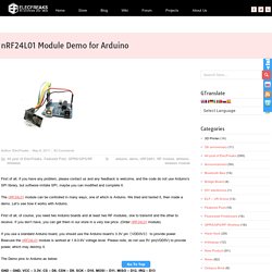
The nRF24L01 module can be controlled in many ways, one of which is Arduino. We tried and tested it, then made a demo. Let’s see how it works with Arduino. First of all, of course, you need two Arduino boards and at least two RF modules, one to transmit and the other to receive. If you don’t have, you can get them in our store in a very low price. If you use a standard Arduino board, you should use the Arduino board’s 3.3V pin(VDD3V3) to provide power.
Web controlled home automation. Description This post is the last of three and describes the software needed to build a web controlled home automation center.
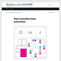
The previous two describes how to add a serial interface to a router and how to build a microprocessor lab board. Features Software for the router (OpenWrt)Software for the web server (html and CGI)Software for the lab board (PIC16F628 assembler)Protocol for serial communication between router and lab boardProtocol for 433MHz radio (and html generation tools) Development My first project for the web access lab board is an Internet controlled home automation system. In a way using a separate microprocessor for the radio communication is overkill.
Electronics - Henning Karlsen. Andys Workshop. Hardware Development. PixelPusher Tensegrity "Twister" - Hackster.io. Projects. Arduino for Beginners. 35. Driving the Bi-Colour 8 x 8 LED Array Properly. The last post shows a bi-colour 8 x 8 but it's only by disconnecting the reds and connecting the greens, and vice versa, that you can get them both going.
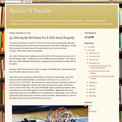
To get them going at the same time in the same sketch, you need a bit more circuitry...that's what I mean by 'properly'.As I said in the last post, building a circuit for the 8 x 8 bi-colour array was one of the first things I tried. I soldered it up on a Perfboard and it worked! I don't know why, but I dismantled the whole thing, probably because it looked a mess with all the wires.Anyway, I didn't document it so here it is again on breadboard - documented this time!
8x8 LED Matrix Scrolling Message Changing In Serial Monitor. Arduino 8x8 LED driving game. Arduino Scrolling 56x8 LED matrix.
Infrared Proximity Sensing Coffee Table Module & Color Changing Glowing Faucet. Lab 12: Basics of LED dot matrix display. We covered how to interface seven segment LED displays to a PIC microcontroller in two sections: Lab 6 and Lab 11.
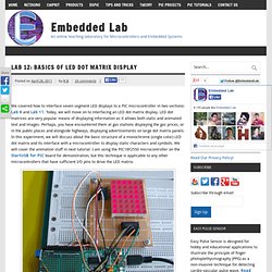
Today, we will move on to interfacing an LED dot matrix display. LED dot matrices are very popular means of displaying information as it allows both static and animated text and images. Perhaps, you have encountered them at gas stations displaying the gas prices, or in the public places and alongside highways, displaying advertisements on large dot matrix panels.
Nerd Club. Matrix led display controlled by Arduino and Android. Hello Arduino fans, first i want to say big thanks to everyone who have been reading our blog recently.
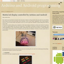
Every day when we see statistics about readers and see that we've been read in Emirates, France, Italy, Russia, Switzerland, USA, United Kingdom, and so on, and of course Serbia, that means a lot for us, and we get more motivation to keep writing about stuff we and you like. In this post, we well be talking about realisation of LED matrix display controlled by Arduino and Android.
Step02_Pins_and_Wiring - ysm-1288cr3g2c - Identify pins and how to wire everything together - How to use a Red/Green Dual Color LED Matrix by Patrick Cutno. The pin-outs provided in the datasheet are confusing difficult to understand.
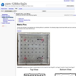
The following images should help identify each pin as well as which pin connects to the correct MAX7221 pin. Datasheet !!!
UPDATE!!! Anode pins are shown in reverse below. As you can see from the above pin-outs of the matrix, almost all of the pins of the MAX will be plugged into to matrix. The resistor you picked out earlier will connect the ISET to Vcc.
How to get an 8x8 LED Matrix working with an Arduino the simple way.
I bought myself an Arudiuo, it cost about $30 and basically lets me prototype electronics.
It gives me a whole heap of input and outputs that I can use to input stuff into the computer, output stuff from the computer or just have it running by itself. The first project I built was just some LED’s and flashing them, this second project is an 8×8 LED Matrix that I bought online off ebay. It cost me $16AUD with free postage for 10 of them. Here is a video of it in action: There was little documentation on the thing, so I had to work it all out myself.
Code, circuits, & construction. Problem with led matrix 8x8 with 24pin. A few random KiCad components, RGB LED stuff mostly. Even though I’ve been using KiCad on and off for a year now, I haven’t really made a lot of my own custom components.
Basically the built-in have more or less sufficed, and if not there are literally thousands more custom made by other users. Anyway, here they are, a very few ones. I also try to get the 3D shapes right for these using Wings 3D. . Btw, to use these components most efficiently in KiCad, I have a suggestion, though it might work best for linux systems. in short it involves making a symbolic link pointing to a KiCad project folder. And the symlink should be inside the KiCad share folders. Of course, no guarantee on the correctness or fitness for any particular or general purpose either…Use at your own risk.
Fun with 8×8 LED Matrix. I’ve finally got around to wiring up my 8×8 LED Matrix and now it’s time for some fun with it. Though out playing with this I’ve learnt about shift registers and how we can use them along with a transistor array chip.
First things first, have a read and look through the Arduino’s ShiftOut guide as they are very well put together (keep re-reading it if it doesn’t make sense): To summarise the guide: A shift register allows you to have 8 outputs while only using 3 pins on the ArduinoYou send a byte to the shift register which has 8 bits (e.g. 10010000)You can combine shift registers so instead of having only 8 outputs you can have 16 when using 2, 24 when using 3, and so onWhen combining shift registers, instead of sending out the 8 bits to the first register and 8 to the second register it’s actually reversed, so the first 8 bits you send are actually for the second register and the next 8 bits go to the first register.
Connecting a 1602A LCD display and a light sensor to Arduino UNO. This tutorial shows how to connect the 1602A LCD display and a light sensor to your Arduino (UNO) and display the light intensity on the screen. I am using only parts from the Arduino starter kit I got from Deal Extreme. This is one of the first things I try with the Arduino, but since I could not find one tutorial that covered the combination of using the LCD screen ánd the light sensor, I decided to write one beginner tutorial. Also there are many different versions of the 1602 LCD display with different pinouts and I couldn't really find which the DX version exactly was. Materials used 1 x Arduino UNO 1 x Breadboard (63 columns) 1 x Light sensor 1 x 50K pot meter 1 x 1602A LCD display 1 x 10K resistor 1 x Connector (16 pins) 1 x USB cable The LCD display The LCD display comes with no connector by default.
Connecting the display and breadboard. Adding a LM75 temperature sensor to the Raspberry Pi. How to Make a Raspberry Pi Web Server. Raspberry Pi temperature logger. PiLogger. Welcome to Pilogger... Instead of having multiple different code fragments around the site for datalogging I thought a bit of consolidation was in order.
RaspberryPi @Homelabs » RaspberryPi the Arduino Development Tool. Not really too much to say here. There has been much talk on the forums about using arduino and similar systems to provide additional IO capabilities for the RaspberryPi.
Yigit Altay
TRS Drawbot. Once you get the hang of using TRS Drawbot, experiment with the different effects you can create by changing pens, substituting in other marking tools like pencils or crayons, working on different types of paper, adjusting the hardware, and tweaking the WAVE synthesizer parameters.
Pens that "bleed" into the paper can create interesting effects at slower drawing speeds. For instance, dramatically increasing the endpoint "dwell" time in the WAVE Synthesizer code to a second or longer causes an interesting "connect-the-dots" effect with a felt-tip marker. Likewise, the amount of sliding friction under the forearm will affect line quality. If the forearm does not make contact with the page surface at all, and is resting only lightly on the pen tip, the pen's movements will be faster but less stable; sometimes a "shaking" phenomenon occurs that creates an interesting sketch-like effect.
A Touchless 3D Tracking Interface. Arduino LM35 Sensor. Weekly Challenges: Archive. Weather shield. There are many shields available almost for every application.
Arduino, Netduino, Rasperry Pi!
Muskox/arduino_env_monitoring.
Arduino Aquaponics: EnvDAQ with Water Temperature Sensor. The Environment DAQ is an open source Arduino shield used to track air temperature, relative humidity and light in aquaponic and hydroponic grow beds. An equally important parameter to track is root temperature and with the new prototyping area on the v2 Environment DAQ boards, it is easy to add a new sensor.
Ohm's Projects. Environmental Monitoring with Arduino. As a software engineer, I love walking into our server room hearing and seeing the sounds and sights of our machines. Fans whir and LEDs blink while the HVAC unit provides a low bass rumble blowing cold air into the CPU cores.
If everything is going right, this room should stay at a constant temperature. However, this is not always the case. Environmental monitoring and alerting is a way to be notified when the temperature is out of the desired range.
Custom Arduino Shield and Sensors. Overview:
Bildr. Arduino Project: Tiny Temperature Shield. Target Amount: $32 / $2000 Amount Raised will be updated once daily.
How to Connect a Buzzer to an Arduino Uno. Arduino Tutorials. Tutorials. My Projects. Installing Ino on a Raspberry Pi. Raspberry Pi with Arduino. Internet of Things Platform. Automate Your Garden With HavestGeek’s Plant Monitoring Technology HarvestGeek - Gallery Page 2. Tutorial - Arduino Jaycon Systems LLC. Tracker - Aquaponic System Management In the Cloud - Iowa Aquaponics.
How to make a light sensor switch. Arduino + Raspberry Pi + Sending data to the web. Raspberry Pi and Arduino Projects and Accessories on Pinterest. Fritzing. Internet-of-Growing: APDuino Project / CUBE-0. Aquaponic DIY Automation Blog. Business Intelligence for Beer In...
Internet of Things Platform. Home Page - LCD Industrial Color Touchscreen Open Frame All-in-one Monitors.
