
Arduino Lesson 16. Stepper Motors. Kinect-Controlled Delta Robot (WIP) H-Bridge on a Breadboard. Arduino With L298N Based Dual Motor Controller. The ControllerA motor controller is a device that serves to govern in some predetermined manner the performance of an electric motor.
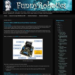
A motor controller might include a manual or automatic means for starting and stopping the motor, selecting forward or reverse rotation, regulating the speed and torque, and protecting against overloads and faults. This Dual Motor Controller is easy to use, thank's to the L298N motor driver chip. This chip allows for direct drive of two bi-directional DC motors, and incorporates high-speed short diodes for protection. Drive current up to 2A per motor output.
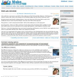
The driver uses a broad-brush design to reduce wire resistance.Below, an illustration of the DRI0002, an inexpensive board avalaible by DFRobot. Click the image to enlarge Each motor is controlled by two pins on the motor controller: A pin M, (zoom the above picture, look at the motor logic) that affects the polarity on the output terminal of the corresponding motor. Click the image to enlarge. PWM with l293/l298. I hit a wall when I was trying to use PWM on the enable pins of both l293 and l298.
Whatever PWM frequency I choose it seems that I loose a lot of torque on the l293/l298 outputs with the PWM at maximum (255). Browsing around searching for implementations I have seen that most of the time PWM is used on the enable pins, but on some (very few) designs I have also seen PWM on the input pins. The question is: which is best/recommended? PWM on the enable pins or on the input pins? Second question: I did use an Attiny clocked at 16 mHz when testing with all prescalers available, but the best results seem to be at no prescaler at all so pretty high frequency.
Third one: In the Atmel datasheets they recommend using phase and frequency correct PWM for motor application, but it seems to work better with fast PWM. Using Motor Bridges. Bridges allow your robot to control high current motors.
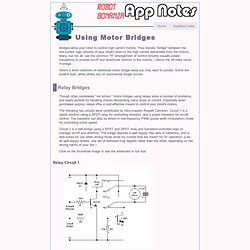
They literally "bridge" between the low-current logic circuitry of your robot's brain to the high current demanded from the motors. Many, but not all, use the common "H" arrangement of control circuitry (usually power transistors) to provide on/off and directional controls to the motors -- hence the oft-cited name H-bridge. Here's a short collection of additional motor bridge ideas you may want to ponder. Some are scratch built, while others rely on commercial bridge circuits. Relay Bridges Though often considered "old school," motor bridges using relays solve a number of problems, and easily provide for handling motors demanding many amps of current.
The following two circuits were contributed by robo-maestro Russell Cameron. Circuit 2 is a half-bridge using a SPST and SPDT relay and transistor-controlled logic to manage on/off and direction. Click on the thumbnail image to see the schematic in full size. Relay Circuit 1. Motor Controllers. In this tutorial I will introduce various motor controller circuits for DC motors and stepper motors (uni-polar and bi-polar).
Where appropriate I will give an idea of guideline costs - based on prices at Digikey as of summer 2008. These costs will assume that you are adding the controllers to an existing robot project and so will exclude the costs of the motors, wiring, soldering equipment, circuit board etc and focus purely on the cost and capability of the crcuit. Each controller has an Eagle schematic but the implementation ie strip board, matrix board, hand crafted PCB is up to you. For those unfamiliar with Eagle then I suggest that you download the free/light version. Familiarity with the concept of 'H-Bridges' is assumed because it is explained very well by others, either on this forum or via Google or Wikipedia. Why do I need a controller? Adafruit Motor Shield. Motor Driver Shield for Arduino. The board uses two L293D chips.
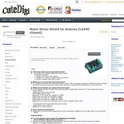
Each one has two H bridge that can controls two motors. Q: How many motors can be connected at most? A: 4 DC motors, or 2 stepper motors and 2 servo motors. Following are options: 1. 2. 3. Dual l293d motor shield datasheet. Motor Shield - Arduino motor/stepper/servo control. Motor Driver Shield L293D. NEW!
Easy Credit Card Payments. YourDuino.com is proud to help sponsor STEMteachersNYC Arduino workshops! More information: STEMteachersNYC <STEMteachersNYC.org> STEM Teaching Workshop: Controlling the Real World – Arduino Programming Sunday, May 18, 10:00 am – 1:00 pm. Reserve your seat: < WHERE: Columbia Teachers College, 525 West 120 St., New York, NY (#1 train to West 116th St/Columbia Univ., or M4, M5, M11, M60, or M104 buses to West 120th St.) COST: $12.00 plus reservation fee (receipts & certificates available) WHO SHOULD COME? STEAM (Science-Tech-Engineering-Art-Math) teachers especially those interested in creative, engaging uses of technology. University High School for Boys, Manhattan) ORGANIZER: Fernand Brunschwig, Math, Sci. & Tech.
The Updated Basic Robot Kit and Starter Sets are available for shipping to the USA NOW. UNIVERSITY STUDENTS: Sign up for an account and email terry@yourduino.com to set Educational discount!