
Build Your Own Seismometer. 2 channel RF remote control. Introduction How many times you needed some remote control to handle some electric device ?
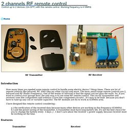
Many times. There are lot of remote controls like infrared, RF, SMS (like my other circuit) and more. The basic small-range remote controls are 2, Infrared and RF (Radio Frequency). One of the weaks of Infrared is that the signal can not pass the walls. I have designed this remote control considering : a.) the verification of the received data because many other devices are working in this frequency (418MHz) b.) and the power-saving of the transmitter.
Features Transmitter description Schematic of the transmitter The transmitter is constituted by AT90S2323 microcontroller and TLP-418A RF transmitter module that works at 418MHz. Mini Van De Graaf... M & M style! - Instructables - DIY, How. In keeping with the purest standards of junk craft, I refused to purchase anything for this project.
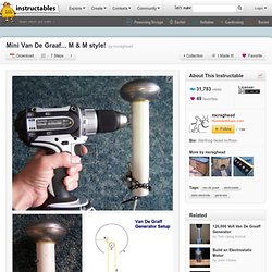
But over time I was able to extract the following from my various hoards of trash: Here's a great reference: (The diagram I've posted is from that page) Howcast. HTML document for the World Wide Web. Back to Projects Page!
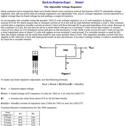
Home! The Adjustable Voltage Regulator Many amateurs have stopped by their local Radio Shack store and have noticed the famous LM317T adjustable voltage regulator. But, did you know that all voltage regulators are adjustable? MAKE: Blog: SMD Soldering (surface mount device soldering) SparkFun has a great SMD Soldering lesson (part of their learn how to make a Simon kit class) – Link.
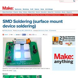
Related: HOW TO – SMD soldering (Surface mount devices) – Link. HOW TO – Salvage surface mount components – Link. Surface mounting with hand-soldering tools – Link. SMT Soldering time lapse – Link. MAKE: Blog: HOW TO - Make video spy glasses. Oh Nooo!
A 404 Page! Looks like we can't find the page that you are looking for. Sorry about that. Let's see if we can make it up to you. First off, let's try searching for the content. If that doesn't work, why not try browsing from popular categories? Low speed AVR oscilloscope - The World's Biggest Show & The Sterling Engine, absorb energy from candles, coffee, and mor. Easy,Cool, and FUN!!!!!!!!! - The World's. MAKE: Blog: Make a Joule Thief - Weekend Projects Video Podcast. DIY - Electronic Speed Control.
Converting a computer ATX power supply to a really useful lab po. Computer power supplies cost around US$15,but lab power supplies can run you $100 or more!
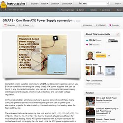
By converting the cheap (free) ATX power supplies that can be found in any discarded computer, you can get a phenomenal lab power supply with huge current outputs, short circuit protection, and very tight voltage regulation. In this instructable I will show you how to quickly convert one of those many computer power supplies into something that you can use to power your electronics projects, for electroplating, for electroetching, for heating wires for foam cutting, etc.
Evil Mad Scientist Laboratories - A Simple and Cheap Dark-Detect. Here’s a simple problem: “How do you make an LED turn on when it gets dark?”
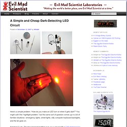
You might call it the “nightlight problem,” but the same sort of question comes up in a lot of familiar situations– emergency lights, street lights, silly computer keyboard backlights, and the list goes on. Solutions? Lots. The time-honored tradition is to use a circuit with a CdS photoresistor, sometimes called a photocell or LDR, for “light-dependent resistor.” (Circuit Example 1, Example 2.) Hacked Gadgets - DIY Tech Blog » Blog Archive » Oscilloscope Tut. Welcome to elwire.com your EL Wire, aka electroluminescent wire. How to Solder EL (Electroluminescent) Wire - The World's Bi. Kelvin's Thunderstorm - Create lightning from water and gra. Convert an ATX Power Supply Into a Regular DC Power Supply! - In. Make a Voltage Controlled Resistor and Use It - Instructables. How to make an H-bridge - Instructables. An H-bridge is a type of circuit that you can use to get a reversible DC motor to spin both clockwise and counterclockwise.
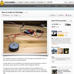
In other words, this circuit allows you to quickly reverse the direction a motor is spinning by using a switch or controller chip to change its direction. I'm going to show you how to make the simplest and most reliable form of H-bridge that I know how to make. I must warn you that this is by no means the best H-bridge design and, in fact, it has a couple shortcoming which I will explain later. The Hilsch vortex tube : step 2. Look below at the schematic I made.
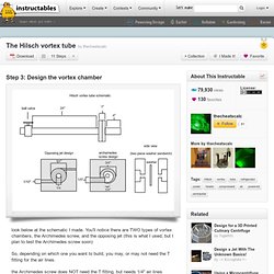
You'll notice there are TWO types of vortex chambers, the Archimedes screw, and the opposing jet (this is what I used, but I plan to test the Archimedes screw soon) So, depending on which one you want to build, you may, or may not need the T fitting for the air lines. the Archimedes screw does NOT need the T fitting. but needs 1/4" air lines the opposing jet design DOES. can use either 1/4 or 1/8 lines now, the archimedes screw all that's different about it, is that you need to drill ONE hole instead of two, and you must design the one spin spiral (does not need to be perfect, just has to be smooth) we'll discuss the two opposing jet design. How to MAKE PV Solar Panels. Soldering tips and tricks. How to Build a Bench-Top Power Supply. All of the following components can be found at your local RadioShack.
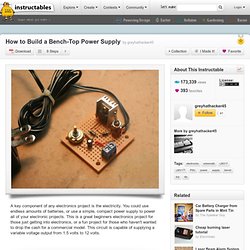
You can also scavenge most all of these parts fairly easily from old electronics. 1 LM317T Adjustable Voltage Regulator - 276-1778This is the adjustable voltage regulator. It takes input from two resistors (R1 and R2) and then ratchets the voltage down accordingly. Interactive Multitouch Display. This multitouch display screen design is based on the description in Jeff Han's paper, Han, J. Y. 2005. Make a wall avoiding Robot! More Open Source Science - Determine the Acceleration due to Gra. Peel off the protective plastic and start putting on the electrical tape. Oscilloscope. Cheap, Easy Light Probe : intro. I teach high school physics and I use a lot of expensive probeware to collect data. The only reason I can do this is my school has been collecting the probes over a number of years, building our collection slowly over time.
For those who aren't science teachers, probeware refers to a collection of interfaces used to connect a variety of sensors to a computer or graphing calculator. These interfaces can allow for real time data collection and graphing or can serve as data-loggers collecting data over time. The two largest vendors of educational probeware are Vernier and Pasco:- Not every school has the ability/money to do probeware based labs, however.
Total cost is less than $5, but you need a computer with an oscilloscope program installed. Electromagnetic Floater : intro. This Instructable will show you how to make a device that can float almost any object with a magnet in it. It is much like the floating globes you can buy, except it works by balancing the forces of permanent magnets with electromagnets, rather then simply using combinations of permanent magnets. This is done by using a microcontroller and an IR sensor to detect where an object is floating below. Then based on a set value, the microcontroller uses the electromagnets to to hold the floating object at a given height. The place the object floats at depends on the weight of the object and the power of the magnets in the object. The height is set by holding the object under the magnets and sensor and pushing the button.
I decided to make the electromagnetic floater because I have always been fascinated by the floating globes in the store, but I never wanted to pay their prices, and I never liked how they only floated objects that you had to buy or came with it. Pulling apart a desktop hard drive to get rare earth magnets. : Laser Doodle. This is the world's cheapest laser light show... It converts your voice and sounds to laser patterns. I made the first one years ago with my dad. Make a Solar Heated Balloon.
Charlieplexing LEDs- The theory. This instructable is less a build you're own project and more a description of the theory of charlieplexing. It's suitable for people with the basics of electronics, but not complete beginners. I've written it in response to the many questions I've gotten in my previously published Instructables. Use that old PC Power Supply as a high current +3.3, +5 or +12 v. Try using an old but still working case fan. Blinkybug (Maker Faire version) UPDATE: Blinkybug Kits, which include all the parts to make 4 bugs, are now available on Make Magazine's online Maker Store.
Blinkybugs are small, eletro-mechanical insects that respond to stimulus such as movement, vibration, and air currents by blinking their LED eyes. They're incredibly simple, yet have a certain lifelike quality. I've been making variations of these for a while now, and showing others how to make them at museums, fairs, workshops, etc. It isn't rocket science, but there's some tricky soldering involved, and they usually take a person at least an hour to put together for the first time. A simple homopolar motor. Mechanical Wave Driver for Chladni Plate. How To: Make Non-Newtonian Fluid (& Experiment with it!) Cheap and Easy Toner Transfer for PCB Making. Collecting Hydrogen and Oxygen. Beer Tin Barometer. Help: An Absolute Beginner's Guide to 8-Bit AVR Programming.
If you'd like to test the waters of microcontroller programming, the new AVR Dragon by Atmel Corporation is a nifty, low-cost entry-level development tool. Unfortunately, right out of the box, the AVR Dragon is not the definitive answer for the beginner looking for an all-in-one solution. Wall transformer for project power supply. Touch Solutions by TVI Electronics. Electronics Lab - Home.