
Untitled. Untitled. ESP8266 0.96 inch OLED Display with Arduino IDE. This guide shows how to use the 0.96 inch SSD1306 OLED display with ESP8266 using Arduino IDE.
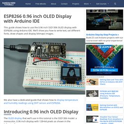
We’ll show you how to write text, set different fonts, draw shapes and display bitmaps images. We also have a dedicated guide that shows how to display temperature and humidity readings using DHT sensor and ESP8266. Introducing 0.96 inch OLED Display The OLED display that we’ll use in this tutorial is the SSD1306 model: a monocolor, 0.96 inch display with 128×64 pixels as shown in the following figure. The OLED display doesn’t require backlight, which results in a very nice contrast in dark environments.
The model we’re using has four pins and communicates with any microcontroller using I2C communication protocol. OLED Display SSD1306 Pin Wiring. IvanMiranda.com. This week I needed some time, so I made a clock.
This clock as it is has the following features: Full RGB control. Auto time set via NIST server. USB powered. WIFI enabled. Can be printed in any printer with a bed 180x180mm or bigger. If more brightness needed 144 led/meter leds can be used if less brightness required 30 led per meter strips can be used. Modular design, if required for any other application more digits can be aligned together for a counter for example. Guide for WS2812B Addressable RGB LED Strip with Arduino. This post is about the WS2812B LED strip, which is an addressable RGB LED strip.
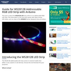
The information in this post also works with other similar LED strips, such as strips of the WS28XX family, Neopixel strip and others. Introducing the WS2812B LED Strip The WS2812B addressable LED strip comes in several models that differ in size, sealant or LED density.
How to read DS3231 Internal temperature sensor, example code. The DS3231 RTC temperature sensor – Arduino & ESP8266 stuff. The DS3231 RTC is a rather accurate RTC that has an internal temperature sensor that is used to calibrate the oscillator.
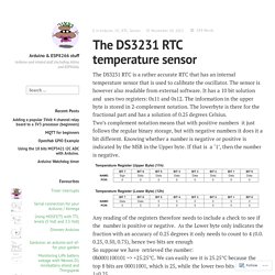
The sensor is however also readable from external software. It has a 10 bit solution and uses two registers: 0x11 and 0x12. The information in the upper byte is stored in 2-complement notation. Convert picture to C code array.
Image to Adafruit OLED Bitmap Converter. Amazon.co. An excellent starter kit, carefully packaged, with high quality components.
I tested it along with the lessons on Adafruit, and the components it is missing in order to get through those lessons are: L293D IC, motor controller, PIR (passive infrared sensor). After you have completed those lessons you will still have the following to play with: joystick, ultrasonic sensor, temp/humidty dht11 module, IR remote/receive, tilt switch, 7 segment displays, 5v relay, stepper driver board.
So a comprehensive kit that should keep you occupied. I calculated how much it would cost to get all these items on Banggood and it came to exactly $30, not including the box or battery, and calculated according to unit cost - you'd actually be spending closer to $50 because of the necessity of buying things in packs of three or five. 16mhz output from atmega 328 to replace crystal on another chip.
How do you use SPI on an Arduino? - Arduino Stack Exchange. Introduction to SPI The Serial Peripheral Interface Bus (SPI) interface is used for communication between multiple devices over short distances, and at high speed.

Typically there is a single "master" device, which initiates communications and supplies the clock which controls the data transfer rate. There can be one or more slaves. How do you use SPI on an Arduino? - Arduino Stack Exchange.
Esp8266. Arduino camera. Search results for "shield geda" Dangerous Prototypes. Packet radio and the Arduino Radio Shield Packet radio is a means of sending data wirelessly over radio channels, and is often used by Amateur Radio Operators.
(One form is APRS, described in our earlier post.) In the video following the break you get some idea of … Read more Arduino-Processing-RFID sandwich game. Interrupts. Structuring Timer Interrupts. Timer setup code is done inside the setup(){} function in an Arduino sketch.
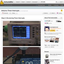
The code involved for setting up timer interrupts is a little daunting to look at, but it's actually not that hard. I pretty much just copy the same main chunk of code and change the prescaler and compare match register to set the correct interrupt frequency. The main structure of the interrupt setup looks like this: Notice how the value of OCR#A (the compare match value) changes for each of these timer setups. Arduino Blag: Timer2 and Overflow Interrupt: Let's Get Cooking. Anybody can open up the example code and make an LED blink, but do you know how to do this with timers and interrupts?
It's important to know your microprocessor fundamentals or you're going to be spending a lot of time on the forums and wading through Google searches. If you read the previous blog post you might remember the problem I mentioned when using the delay function. Using the function locks up the processor and prevents any other code from running until it is done waiting. One simple way to get around using the delay function is to use timers instead. There are a six available timers in the Arduino Mega. Mini. To get started with the Arduino Mini, follow the directions for the regular Arduino on your operating system (Windows, Mac OS X, Linux), with the following modifications: Connecting the Arduino Mini is a bit more complicated than a regular Arduino board (see below for instructions and photos).
You need to select Arduino Mini from the Tools | Board menu of the Arduino environment. To upload a new sketch to the Arduino Mini, you need to press the reset button on the board immediately before pressing the upload button in the Arduino environment. Information about the Arduino Mini The microcontroller (an ATmega328) on the Arduino Mini is a physically smaller version of the chip on the USB Arduino boards, with the following small difference:
Tachometer. Proto Advantage - QFN-38 to DIP-42 SMT Adapter (0.5 mm pitch, 5 x 7 mm body, 3.5 x 5.5 mm pad) Proto Advantage - QFN-40 to DIP-40 SMT Adapter (0.5 mm pitch, 7 x 5 mm body) Ultrasmall Arduino. Electronics : Microprocessors : Interrupts. This article discusses interrupts on the Arduino Uno (Atmega328) and similar processors, using the Arduino IDE. The concepts however are very general. The code examples provided should compile on the Arduino IDE (Integrated Development Environment). When writing an Interrupt Service Routine (ISR): Keep it shortDon't use delay ()Don't do serial printsMake variables shared with the main code volatileVariables shared with main code may need to be protected by "critical sections" (see below)Don't try to turn interrupts off or on.
Lecture7. Logic Level Converter. Description: If you've ever tried to connect a 3.3V device to a 5V system, you know what a challenge it can be. The SparkFun logic level converter is a small device that safely steps down either 5V signals to 3.3V or steps up 3.3V to 5V. This level converter also works with 2.8V and 1.8V devices. Each level converter has the capability of converting 4 pins on the high side to 4 pins on the low side with two inputs and two outputs provided for each side. The level converter is very easy to use. Connect a 3.3v to 5v level shifter to the Arduino.
The Arduino used in the this tutorial is a 5v model so we need to convert the 3.3v signal coming out of the G1 using a level shifter. It should be possible to connect directly to a 3.3v Arduino but that was not something I tested. There are several ways to approach this but we'll use a 74LS04 chip in this example. Arduino info/vrac. Savage Circuits - Mixed Voltage Systems: Interfacing 5V and 3.3V Devices.
GOduino II = Arduino + L293D Variable Speed Motor Controller. The GOduino II is a self-contained programmable controller for wheel-based robots. It's an Arduino Uno clone plus an L293D motor driver for under $20. It controls both motor direction and speed.The prototype predecessor to this is the GOduino, a basic version of this controller on a breadboard.
I will maintain updates to this guide both here and on my blog I have designed a few basic robots using the Arduino Uno and motor shields. Arduino Pro Mini 328 - 5V/16MHz. Description: It's blue! It's thin! It's the Arduino Pro Mini! SparkFun's minimal design approach to Arduino. This is a 5V Arduino running the 16MHz bootloader. Arduino-Pro-Mini-v12. 3G/GPRS shield for Arduino (3G + GPS) - Shields - Arduino. Labs - Index browse. SparkFun GPS Shield (GPS-10710) GPS/GPRS/GSM Module V2.0 (SKU:TEL0051) Introduction This is a GPS/GPRS/GSM shield from DFRobot. This shield with a Quad-band GSM/GPRS engine works on frequencies EGSM 900MHz/DCS 1800MHz and GSM850 MHz/PCS 1900MHz. It also supports GPS technology for satellite navigation. It's possible for your robot and control system to send messages and use the GSM network.
It is controlled via AT commands(GSM07.07 ,07.05 and SIMCOM enhanced AT Commands). Arduino.