
General Thrust Equation. Thrust is the force which moves an aircraft through the air.
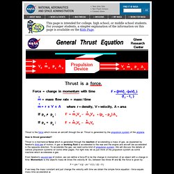
Thrust is generated by the propulsion system of the airplane. How is thrust generated? Thrust is a mechanical force which is generated through the reaction of accelerating a mass of gas, as explained by Newton's third law of motion. A gas or working fluid is accelerated to the rear and the engine and aircraft are accelerated in the opposite direction. To accelerate the gas, we need some kind of propulsion system. From Newton's second law of motion, we can define a force F to be the change in momentum of an object with a change in time. F = ((m * V)2 - (m * V)1) / (t2 - t1) If we keep the mass constant and just change the velocity with time we obtain the simple force equation - force equals mass time acceleration a F = m * a If we are dealing with a solid, keeping track of the mass is relatively easy; the molecules of a solid are closely bound to each other and a solid retains its shape.
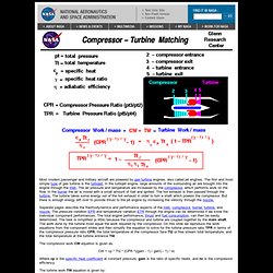
M dot = r * V * A F = d(mv)/dt or F = (mv)dot. Turbine Nozzle Performance. Compressor-Turbine Matching. Most modern passenger and military aircraft are powered by gas turbine engines, also called jet engines.
The first and most simple type of gas turbine is the turbojet. In the turbojet engine, large amounts of the surrounding air are brought into the engine through the inlet. The air pressure and temperature are increased by the compressor, which performs work on the flow. In the burner the air is mixed with a small amount of fuel and ignited. The hot exhaust is then passed through the turbine. Separate pages describe the thermodynamics and performance aspects of the inlet, compressor,burner, turbine, and nozzle.
The compressor work CW equation is given as: CW = cp * Tt2 * (CPR ^((gam - 1) / gam) - 1) / nc Where cp is the specific heat coefficient at constant pressure, gam is the ratio of specific heats, and nc is the compressor efficiency. The turbine work TW equation is given by: TW = nt * cp * Tt4 * (1 - TPR ^ ((gam -1) / gam)) where nt is a turbine efficiency factor. Activities: Thermodynamics for Dummies. Gltrs.grc.nasa.gov/reports/2005/TM-2005-213658/TM-2005-213658.pdf. Www.stanford.edu/~cantwell/AA283_Course_Material/AA283_Course_Notes/Ch_04_Turbojet_Cycle.pdf. Power Turbine Thermodynamics. Burner Thermodynamics. Turbine Engine Thermodynamic Cycle - Brayton Cycle.
To move an airplane through the air, we have to use some kind of propulsion system to generate thrust.
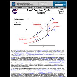
The most widely used form of propulsion system for modern aircraft is the gas turbine engine. Turbine engines come in a variety of forms, including turbojets, turbofans, and turboprops, but all of these types of engines have some things in common. All turbine engines have the core components of a compressor, combustion section, and power turbine which drives the compressor. The thermodynamics of all turbine engines are similar. To understand how a propulsion system works, we must study the basic thermodynamics of gases. On this page we discuss the Brayton Thermodynamic Cycle which is used in all gas turbine engines. The Brayton cycle analysis is used to predict the thermodynamic performance of gas turbine engines. Activities: Guided Tours Navigation.. Beginner's Guide Home Page. Power Turbine. Most modern passenger and military aircraft are powered by gas turbine engines, which are also called jet engines.
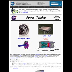
There are several different types of gas turbine engines, but all turbine engines have some parts in common. All gas turbine engines have a power turbine located downstream of the burner to extract energy from the hot flow and turn the compressor. Work is done on the power turbine by the hot exhaust flow from the burner. Description of Images The bottom of the figure shows: computer drawings of a turbojet with the location of the turbine relative to the other engine components, on the right the turbine section alone with the central shaft attached to the turbine, on the left.