
RF Links Tutorial w/Arduino. Arduino and NFC (part 1) - ls6's posterous. NFC & RFID on Android. 433Mhz RF link kit. Introduction The kit is consisted of transmitter and receiver, popular used for remote control.
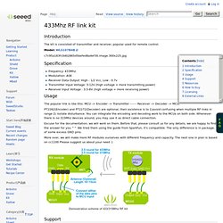
Model: WLS107B4B Specification Frequency: 433Mhz. Modulation: ASK Receiver Data Output: High - 1/2 Vcc, Low - 0.7v Transmitter Input Voltage: 3-12V (high voltage = more transmitting power) Receiver Input Voltage : 3.3-6V (high voltage = more receiving power) Usage The popular link is like this: MCU -> Encoder -> Transmitter ------ Receiver -> Decoder -> MCU, PT2262(Encoder) and PT2272(Decoder) are optional, their existence is to 1)avoid confusing when multiple RF links in range 2) isolate disturbance. Excuse for the documentation, we will work on them. More over, we will make more RF modules ourselves with different frequency and capacity. Support If you have questions or other better design ideas, you can go to our forum or wish to discuss. Resources How to buy Click here to buy: Licensing External Links RCSwitch - Arduino Library to control 433Mhz remote power sockets.
433M RF Wireless Module A Pair of Receiver and Transmitter. * Prices depends on each individual modules and real price (including discount) Get Them Separably here: Features: The excellent performance of the receiver module, using a digital process technology, with a strong anti-interference, stable performance, high reliability, non-directional, long life, undisturbed Japan imported chips, high stability, low power consumptionsimilar remote control does not have any interference garbled phenomenon, the transmitted signal of the wireless receiver, remote control distance, can pass through walls, no direction.
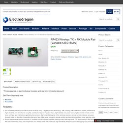
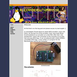
Supporting the use of any of the same frequency remote control can be and market fixed code, learning code.Super-regenerative receiver module LC oscillator circuit includes amplifier shaping output data signals to TTL level directly to the decoder, the use of extremely easy, and inexpensive, it is widely used. Receiver module specification: Transmitter Module Specification: We tried them using the guide from Sparkfun, it’s compatible. Alexanderguthmann.de. The emulator scheme The emulator design: 1.Microcontroller, Atmega 8, 8Mhz 2.Level Converter, MAX232 3.Stabilizer, 7805 4.Crystal, 8Mhz 5.Control LED 6.Power LED 7.Power connection 8.Coil connection 9.Reset Bottom 10.ISP connection 11.RS232 connector.
Stupid Simple Arduino LF RFID Tag Spoofer. HandheldRFIDReaderv1_0. Final Design Project - RFID Proximity Security System. Proximity Security System By: Craig Ross (cjr37) and Ricardo Goto (rhg22) Introduction and Motivations: For our final project, we designed and built (and exhaustively tested) an RFID-based proximity security system for use with Cornell Identification cards, which have been RFID-embedded since fall of 2003.
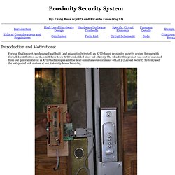
The idea for this project was sort of spawned from our general interest in RFID technologies and the near-simultaneous occurance of Lab 2 (Keypad Security System) and the antiquated lock system at our fraternity house breaking. "Old and Busted...New Hotness" -Will Smith At the highest level, our device uses an antenna coil to power the RFID tag embedded in our Cornell ID's and read the induced response from the card. High Level Hardware Design: Before we start with actual circuit design, it is neccessary to understand the principals behind the technology that this project has set out to harness; passive RFID communications. T55x7. Overview Every access card, keyfob and other types of RFID tags in existence today uses some sort of embedded integrated circuit transponder to perform their RF Identification function.
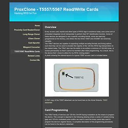
Some of these devices are designed to use a specific encoding format, some are read-only (programmed at the factory), and others like the Atmel T5557 and ATA5567 are extremely versatile. The T55x7 devices are capable of supporting multiple encoding formats and timing options such that they can be used to emulate the majority of the 125 Khz RFID tag transponders on the market today. The T55x7 also has the ability to be written a minimum of 100,000 times, or locked permanently so that it cannot be rewritten after initial programming. As a result, this is the device that I chose to utilize for my RFID cloning project. Reader_Cloner. Reader / Cloner Overview The picture below is of my prototype combination card reader and cloner.
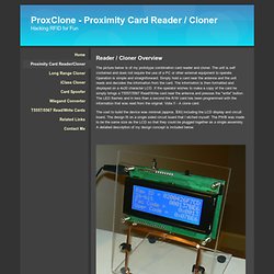
The unit is self contained and does not require the use of a PC or other external equipment to operate. Operation is simple and straightforward. Simply hold a card near the antenna and the unit reads and decodes the information from the card. The information is then formatted and displayed on a 4x20 character LCD. The cost to build the device was minimal (approx. $30) including the LCD display and circuit board. Background I initially began this activity by trying to build a simple card reader that could be used to obtain all of the information that was transmitted by the card during a simple read operation.
The Design A document that I found to be invaluable during my learning process was Microchip's 125 Khz RFID Sysem Design Guide which can be found on their website. Download a PDF version of the schematic here. Schematic.