
Practical Guide to Free-Energy Devices - Chapter 5. 焦耳小偷动画教程(joules thief 60,000)-教育视频. 自由能源装置实践手册(第19页)_科幻奥秘. TALKING ELECTRONICS LED Torch. A LED torch is one of the simplest projects you can build and it's very interesting as it uses a super-bright white LED.
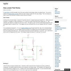
In the history of LED production, red LEDs were the first to be invented and their output was so dim you could barely see if they were illuminated. You needed a darkened room to see them at all. Then came green, yellow and orange LEDs. Colin55 on Joule Thief. How a Joule Thief Works. A Joule Thief is a small low power circuit that uses up almost all the energy stored in its power source.
The circuit is based on the Boost DC-DC converter where the output voltage is higher than the input voltage. The circuit below is a type of Joule Thief that does not require a ferrite toroid core inductor. How it Works: Looking at the schematic below – transistor T2 switches inductor L1 between ground and capacitor C1. When connected to ground, L1 charges up. T2 is controlled by transistor T1. Building it: Unlike the other examples available online, I decided to make a board that did not require me to wire up additional components. With a good battery the circuit runs for about 10 days at full brightness and then slowly dims over the next few days.
Click to enlarge: Building Your Own Interested in building one? Like this: Like Loading... Laser Hacker Alternative Energy. Joule thief - getting power from dead batteries. The joule thief is an electronic circuit that allows you to make use of batteries normally considered dead.
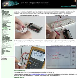
A battery is often considered "dead" when it can't power a particular device. But what's really happening is that the battery voltage is no longer high enough for the device when it's used directly. The joule thief circuit massages the voltage and current coming from the battery so that the voltage is high enough, for periods of time, for the device to work continuously. The LED in the above photo requires 1.85 volts but as the photo below shows, the battery voltage is only 1.27 volts. 焦耳小偷全解释-★精华贴汇总★_极客迷论坛. 焦耳小偷运行过程跟踪分析。_海盗旗. 呵呵,弟兄们,我把我对焦耳小偷运行过程的理解发上来,请弟兄们帮忙给完善一下,共同把焦耳小偷的工作原理彻底弄清楚、搞明白,看看有无可能的增值点在里面,我相信人多力量大,什么东西也架不住人的琢磨与研究,当然,我电子的基础差,很多地方不明白,会存在很多的错误,这些就要靠弟兄们指出来了,下面我就抛砖引玉了~~ 在这次的分析中,采用步步跟踪法来跟踪电子在电路里面的流动、做功情况,对可能的增值点进行推测。

下面是标准的焦耳小偷电路: 工作步骤: 1、按下开关,电子从电池正极流到A点,准备分两路进入两个线圈。 (废话) 2、电流一分为二,准备分别进入基极线圈L1和集电极线圈L2。 3、电流进入L1,L1线圈产生自感来阻碍电流的增大,电磁不分家,有电就有磁,L1产生的自感电流阻碍电流增大,那么他的磁场方向就与电池电流通过产生的要产生的磁场方向相反。 4、跟上面的道理相同,L2线圈用来抵抗电流增大的自感被L1利用,叠加到了L1自己的输出上了。 5、从L1流过的电子和L1从L2自感中获得的电子叠加,施加到三极管的基极,导通了三极管。 6、由于B点和C点原来存在着叠加情况,那么导通之后电压或电流(到底是电压还是电流)或自然下降,以便降低到电池提供的电流的水平。 7、由于BC点都存在着电压或电流的下降,所以L1线圈和L2线圈要阻止这种下降,他会产生出感生电流来叠加到L1和L2的输出方向上。 8、由于自感互相影响,L1用来增加电流的自感被L2线圈感知,产生出感生电流来顶住了集电极电子的流动,同理,L2用来增加电流的自感被L1线圈感知,产生出电流来顶住了L1的电子流动。 9、由于基极电流被阻断,集电极电流也会断开,在断开的那一刻,自感达到了最大值,L1和L2同时产生出更大的自感电流来阻止这种变化,由于三极管不导通,L2产生的感应电流被导向了LED,点亮了LED,L1产生的自感被冲向基极? 10、由于位于同一磁通路径自感相互的影响,L1产生的自感会导致L2产生一个反方向的自感以抵抗自己方向上磁通量的变化,如此说来L2线圈产生的电流会向电源反冲? Joule-Thief-Intro. Joule-Thief-Rewound-pear. Weekend Projects with Bre Pettis: Make a Joule Thief. In this week’s Weekend Projects video podcast, Make Magazine’s Bre Pettis and I show you how to make a Joule Thief.
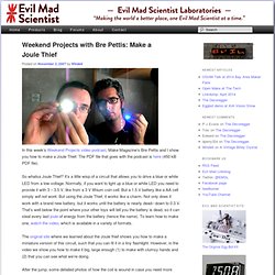
The PDF file that goes with the podcast is here (450 kB PDF file). So whatsa Joule Thief? It’s a little wisp of a circuit that allows you to drive a blue or white LED from a low voltage. Normally, if you want to light up a blue or white LED you need to provide it with 3 – 3.5 V, like from a 3 V lithium coin cell. But a 1.5 V battery like a AA cell simply will not work. The original site where we learned about the Joule thief shows you how to make a miniature version of this circuit, such that you can fit it in a tiny flashlight.
After the jump, some detailed photos of how the coil is wound in case you need more detail than in the video. It’s a little hard to see through my fingers in the video, so here’s the detailed view of the coil and winding your own. To wind your own coil, start with two colors of insulated wire and a bare ferrite toroid. Clip the wire leads down. Wordpress - 2011-12-03 Low Voltage Joule Thief – TN0702 MOSFET. In Jan 2009 I collaborated with Quantsuff and we tried different designs for a low voltage Joule Thief.
The conventional silicon BJT Joule Thief (bipolar junction transistor) has a base to emitter forward voltage of about 0.55 to 0.6 volts, so if the supply is below this voltage it will not start. But once it gets started, it will run to below 0.5V, maybe down to 0.35V. We can change the transistor to a germanium, which is an ancient 1950s transistor technology no longer made. The germanium’s forward voltage is about 0.2 to 0.25 volts, so the germanium BJT Joule Thief will start up at half the voltage of a silicon BJT. But as I said, these are old transistors no longer made and difficult to obtain, and the reasonably priced ones can’t handle a large amount of current and power.
One idea QS had was to use a switch to charge a capacitor when the JT was off. The Law of Diminishing Returns Another problem at low voltages was getting enough power to light the LED reasonably bright. Wave JT - Larson Scanner with Joule Thief. I love LED chasers. A bunch of LEDs neatly turning on and off on a precise timing - lights running one way, then the other way… It's relaxing, soothing, and hypnotic. There are so many LED chaser/scanner/sequencer circuits out there, some are made with discreet transistors, some based on logic ICs, and more and more others are using microcontrollers.
There is one thing in common with all of the LED chaser circuits you find on the net - none of them can operate with just one alkaline battery! Most of us know that LEDs need at least 2.2V or so to light. Blue and white LEDs require even higher, typically 3.2V. Joule thief. The circuit is variant of the blocking oscillator that forms an unregulated voltage boost converter.
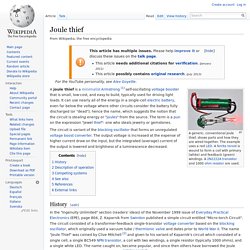
The output voltage is increased at the expense of higher current draw on the input, but the integrated (average) current of the output is lowered and brightness of a luminescence decreased. History[edit] In the "Ingenuity Unlimited" section (readers' ideas) of the November 1999 issue of Everyday Practical Electronics (EPE), page 804, Z. Wave JT - Larson Scanner with Joule Thief.