
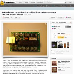
InkJet transfer.
Photo sensitive. Design tool. Making Printed circuit Boards at or Near Home: A Comprehensive Overview, Almost a Guide. There is a bit of controversy over making your own printed circuit boards, many makers think that professional boards are so inexpensive now that they are the way to go.
Others want to have more control and hopefully short turn around time that comes with making their own. This instructable assumes that you buy into the "make your own point of view" and will not argue the point. Near Home is bit of a new idea. What does “near home” mean? There are getting to be more and more hacker spaces ( and similar spaces ) which give makers access to more advanced and expensive equipment than most can afford at home. This instructable will give an overview of most of the popular methods, describe how the steps come together and provide links ( mostly to other instructables, but some offsite ) to material on making boards.
Making boards breaks down into a set of somewhat distinct steps. Note that steps overlap somewhat and are often applied iteratively. InkJet,PCB Etch,Etch PCB, Etchant Resist. This page details the use of Epson^ InkJet printers with pigment based inks to feed and directly print resist patterns to copper clad printed circuit board stock, ready for etching.
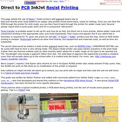
Once you can feed the PCB through the printer for etch resist, you can then feed it back through the printer for solder mask (yes! Several people report that it works quite well!) And for a component "silk-screen". Toner transfer is probably easier to set up for and may be as fast, but direct ink is more precise, allows solder mask and component printing in the appropriate color, and most importantly, finer traces and spaces!
And if you admit that a laminator is required for TT, given the prices for old C84^ or R220^ / R280^ printers and the Inks, direct to PCB InkJet printing is cheaper. The secret (discovered by Volkan) is that certain pigment based inks, such as MISPRO Inks^ (#MISPRO42-SET-MK) can be cured with heat to form a very strong resist. Printer Modifications: CD/DVD printing trays. Process. Converting an Inkjet Printer to Print PCBs. Recently one of my focuses has been to find a way to make the PCB (Printed Circuit Board) creation process easier.
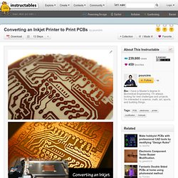
I like being able to design something based on what I want in a circuit and just making it myself on the random weekend. While the toner transfer method has been my go to in the past it’s just not nearly as consistent as I would like it to be. The specific pressure of the iron and timing both make it a hit or miss approach. I’m not a fan of hit or miss I like to know something is going to work every time I try to do it. Direct to PCB InkJet Resist Printing In CD/DVD printing trays. In CD/DVD printing trays Some inkjet printers are designed to print on materials about the thickness of a PCB and even have a carrier to hold the stock: CD/DVD printers!
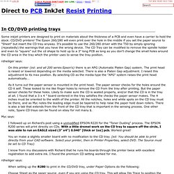
The Epson 260/280 will even print over the hole in the middle if you set the paper source to "Sheet" but insert the CD tray anyway. It's possible to use the 260/280 driver with the T50 by simply ignoring (repeatedly) the warnings that you have the wrong device. DIY Flexible Circuits. I am currently creating flexible circuits for a project I am working on.
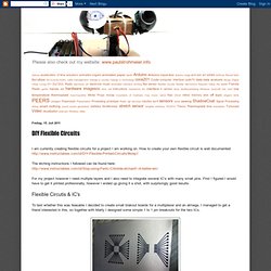
How to create your own flexible circuit is well documented: The etching instructions I followed can be found here: For my project however I need multiple layers and I also need to integrate several IC's with many small pins. First I figured I would have to get it printed profesionally, however I ended up giving it a shot, with surprisingly good results. Flexible Circutis & IC's To test whether this was feasable I decided to create small brakout boards for a multiplexer and an atmega. Here you can see the two circuits printed on pyralux using a solid state printer. Once out of the etching solution and cleaned we went about soldering the components. This is what I learned: - make sure that your circuit design and the IC line up perfectly.
. - make the leads as thick as possible. . - tin the connecting elements and some of the surrounding circuitry. . - glue the circuit in place. Multi-Layerd Flexible Circuits bottom layer Anyway. Stop using Ferric Chloride etchant! (A better etching solution.)