
David Jabon's Blog: The LS7366 Quadrature Counter. Quadrature encoded signals have many applications ranging from simple input/output control (e.g. a volume control on a radio or a knob on a toaster oven) to motor control (e.g., speed and position).
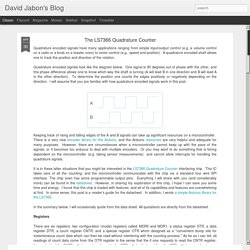
A quadrature encoded shaft allows one to track the position and direction of the rotation. Quadrature encoded signals look like the diagram below. One signal is 90 degrees out of phase with the other, and this phase difference allows one to know which way the shaft is turning (A will lead B in one direction and B will lead A in the other direction). To determine the position one counts the edges positively or negatively depending on the direction. I will assume that you are familiar with how quadrature encoded signals work in this post. Keeping track of rising and falling edges of the A and B signals can take up significant resources on a microcontroller. Feeding a 74hc14 Schmitt Trigger. Optocoupler Circuits - Nuts & Volts Magazine - For The Electronics Hobbyist.
An optocoupler device can be simply described as a sealed, self-contained unit that houses independently-powered optical (light) Tx and Rx units, that can be coupled together optically.

Figure 1 shows the basic form of such a device. Here, the Tx unit is a LED, but the Rx unit may take the form of a phototransistor, a photo-FET, an opto-triac, or some other type of photo-sensitive semiconductor element; the Tx and Rx units are housed closely together in a single, sealed package. Most modern optocoupler devices use a phototransistor as their Rx unit; such a device is known simply as an ‘optocoupler,’ since the input (the LED) and the output (the phototransistor) devices are optically coupled.
Figure 2 shows the basic form of an optocoupler, together with a very simple application circuit. The Figure 2 device is a simple isolating optocoupler. The device shown in Figure 4 is known as a reflective optocoupler. Other important optocoupler parameters include the following. ISOLATION VOLTAGE. Working with the Comparator Circuit. March 15, 2010 by rwb, under Electronics.
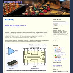
Sometimes in the embedded system world we need to process the analog world and sending the signal to the microcontroller when the analog signal exceed some predetermine limit we’ve set. Some example of this situation is to send the interrupt signal to the microcontroller operation when the temperature is already exceeds certain limit or the light intensity exceeds certain bright level. This is when the comparator circuit becomes handy as it’s designed specially for this purpose. Today the modern comparator is easily found in the form of integrated circuit such as the popular National Semiconductor LM339 quad (four) comparator 14 pins dual in line (DIL) package bellow:
Photodiodes GPIO Question. Arduino Analog Pins: Setting Up A Photo Interrupter (or Slotted Optical) For Digital Pins (Part 2) As I mentioned in the last post, I finally got my photo interrupter to react under the Arduino, using an Analog pin.

Now for my project this was fine, as I had actually allotted one analog pin for this detector, as the digital ones would all be in use. But analog is slow (about 110us), much slower than a digital detect, and I worried this slowness would someday come back and cause problems. So I looked at the circuit I was using, and realized something: the analog output value of 200 was quite low. I was thinking of 255 as the upper limit for analog, but in fact it runs from 0-1023. This means that 200 was about 20% of a full signal, and possibly that was why I couldn’t get a digital reading. Input Interfacing Circuits Connect to the Real World. While computer interfacing uses the unidirectional and bidirectional input and output ports to drive various peripheral devices, many simple electronic circuits can be used to interface to the real world either using mechanical switches as inputs, or individual LEDs as outputs.
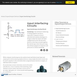
Pushbutton Switch For an electronic or micro-electronic circuit to be useful and effective, it has to interface with something. Input interface circuits connect electronic circuits such as op-amps, logic gates, etc. to the outside world expanding its capabilities. Op-Amp (Thru-Hole) - LM358 - COM-09456. Description: The LM358 is a great, easy-to-use dual-channel opamp.
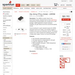
Opamps have so many applications we figured we should probably carry at least one in a DIP package. LM358 applications include transducer amplifiers, DC gain blocks and all the conventional opamp circuits. If you’re looking for a good, standard opamp the LM358 should fill most of your needs. It can handle a supply of 3-32VDC and source up to 20mA per channel. This opamp is great if you need to operate two individual opamps from a single power supply. Features: Input Interfacing Circuits Connect to the Real World. Mouse dual phototransistors. Mouse dual phototransistors. Pinout help for my salvaged ir sensor/photo diode from mouse.? DIY motor feedback from mouse parts. - Page 2 - Parallax Forums. Using the LS7366R SPI Quadrature Counter.
Introduction The LS7366R is a powerful decoder/counter chip which can be connected directly to a motor encoder to count encoder pulses.

Using the LS7366R SPI Quadrature Counter. 3 Steps to Specifying the Correct Encoder Output Type. When it comes to incremental rotary encoders, the number-one configuration error we encounter is the specification of an incorrect output type.
Unfortunately, this can be a costly mistake, leading to a non-functioning encoder or damage to the components or equipment to which it's connected. In few cases can the encoder’s output type be modified by our Repair department. Granted, selecting the correct encoder output type sometimes can be confusing. However, once you grasp a few key concepts, know what questions to ask and problems to anticipate, it becomes fairly straightforward. We've broken the process into three basic steps: Step 1: Determine the number of output channels that are required for the application. "A" Single channel: This option is typically specified to provide position feedback for unidirectional rotation. Sensors - Double Pendulum. You have two options to "decode" the quadrature signal, either through a software algorithm or through a dedicated IC.

Software is probably the path of least resistance, but it has the detriment of adding additional load to the processor. Algorithms specific to the Arduino include: Keith's Electronics Blog - Has an arduino example of a knob and a library for implementing multiple quadrature signals. This might not work because it messes with the PWM signal.Arduino Rotary Encoders - Very basic quadrature decoding, won't work for time sensitive stuff.PIC Quadrature decoder - A couple different ways of decoding quadrature. There are a number of ICs that will take the quadrature signal and turn it into counts. This is pretty cool, because it means that you can get very high fidelity encoding of position with almost no processing cost. ATTiny USI I2C Introduction - A powerful, fast, and convenient communication interface for your ATTiny projects!
I2C, it's a standard that's been around for around 20 years and has found uses in nearly every corner of the electronics universe.
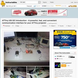
It's an incredibly useful technology for us microcontroller hobbyists but can seem daunting for new users. This tutorial will solve that problem, first by reviewing what I2C is and how it works, then by going in-depth on how to implement I2C in Atmel's ATTiny USI (Universal Serial Interface) hardware. I2C is commonly used in GPIO expanders, EEPROM/Flash memory chips, temperature sensors, real-time clocks, LED drivers, and tons of other components. If you spend much time looking for new, cool parts you'll probably wind up with several I2C parts. Fortunately it is a protocol that is available on most microcontrollers, though it is a bit more complex than others. I2C Tools of Interest: Before you dig too deep into I2C communications, you'll want to have some things on hand that will make your learning experience easier.
Guide to Arduino and AVR Communications. If you spend any time playing with Arduinos, ATtinys or looking at AVR spec sheets, you soon encounter a bewildering smörgåsbord of acronyms for various communication protocols. With examples such as I2C, LIN, SPI, TWI, USI, etc., it can get pretty confusing. Rotary Encoder on the ATtiny85 – Part 2. Using the Arduino PID Library for precise position control of X and Y axis on RepScrap printer. Using the Arduino PID Library for precise position control of X and Y axis on RepScrap printer.
Arduino-Pi Ramblings: Using DC Motors and Encoders for 3D printer: Challenging the norm! Every 3D printer I've seen (please correct me if I've missed something!) Uses stepper motors for X/Y/Z axis. The RepRap firmware assume that you are using steppers in your build.That said, RepRap does introduce the concept of "RepStrap" (from A repstrap is a 3D printer cobbled together from whatever parts you can find, which will eventually allow you to print the parts for a reprap machine, or to simply use as a stand alone machine. Mercury — MicroNova Electronics. Quadrature Encoder too Fast for Arduino (with Solution) » Dr Rainer Hessmer. Atmel AVR XMEGA 64-pin A3U/A3BU/D3/C3 USB development board with level shifter. Why (and how) you should start using XMEGAs. I love the Arduino platform, especially for prototyping, and have been playing with the Atmel ATmega chips for a long while.
Once you’ve designed your project, some of the smaller derivatives (like the Ardweeny I’ve mentioned before) are cheap enough to leave embedded everywhere and, in any case, you can always move from an Arduino device to a DIY board, designed around the same microprocessors. Doc8109. LS7366R. Ams magnetic position sensor products - linear incremental position sensors, easypoint joystick position sensor, rotary position sensor, 3D position sensor. 3 Axis Encoder Conter Arduino Shield - robogaia.com. Quadrature Decoder. LSI CSI - Design and Production of Full Custom and Standard Integrated Circuits. Closed Loop Control For 3D Printers. One of the bigger problems with any CNC machine or 3D printer is the issue of missed steps when moving the toolhead. LSI-LS7366R by ANAHEIM AUTOMATION - Buy or Repair at PLCCenter - PLCCenter.co.uk. LS7366R. Sensors - Double Pendulum. Arduino.
3 Axis Encoder Conter Arduino Shield - robogaia.com. Using the LS7366R SPI Quadrature Counter - Northwestern Mechatronics Wiki. Using the LS7166 Quadrature Counter - Northwestern Mechatronics Wiki. Introduction. Test bench for measuring timing belts lenghts - Freetronics Forum. The work leading up to the finished product: Experiments in Quadrature Encoders. Quadrature encoders are regularly used in robotics to detect and measure movement of the vehicle's drive wheels. Quadrature Encoders in Arduino, done right. Done right. YAMEB: Quadrature Encoders in Arduino, done right. Done right.