
ARDUINO MPPT SOLAR CHARGE CONTROLLER (Version-3.0): 42 Steps (with Pictures) After lot testing we observed that MOSFET ( Q3 ) in ver-3.0 design is burning repeatedly.We tried to modify the existing software but not find any satisfactory result.
The other problem was that MOSFET Q1 ( in V-3.0) conduct even when there is no solar input. To solve the above problems and enhance the power handling capability we are modifying both the hardware and software.This is named as Version-3.1 Charge Controller. This version is not completed yet.So wait until it is complete. Don't worry we are making a solution for those who have made the V-3.0 prototype.After little modification we will able to use the new software. You can see the updates on Hackaday.com This version have 3 options. 1. 5 Amp version : T94-26 toroid, 48 turns of AWG20 wire to give 135 uH (it takes almost 1.5m of wire) Q1, Q2 and Q3 all pairs of IRFZ44N MOSFETs (6 in all). C1 will be 3 * 220 uF low ESR capacitors in parallel, C2 will be a single 220 uF low ESR capacitor 2. 8 Amp version : 3 10 Amp version : Solar Panel Optimizing Battery Charger.
Introduction Like most power generation systems, solar panels (or Photovoltaic Panels, or PV Panels) generate the most power when they are presented with an optimal load.

Figure 1 shows the V-I curve for a typical solar panel (Sharp ND-224U1F), and output power under different lighting conditions. Click on the figure for the panel's full specification. Figure 1 The solar panel behaves like a constant current source at high current, and like a voltage source at low current. The solar panel is typically used to charge batteries since solar energy is only available during the day, but typical electrical power usage extends during dark periods. Batteries operate at a relatively stable voltage which at best may only match the optimum voltage of a solar panel under one set of conditions. Fortunately, switching regulators of the type used in high efficiency battery chargers can vary the load while maintaining the proper output voltage for battery charging.
How it works Figure 2 Figure 3 Figure 4. C2000 Solar MPPT tutorial covering the electronics & C code. In this second part of the C2000 Solar MPPT Tutorial, the hardware and circuit design will be looked at in greater depth.
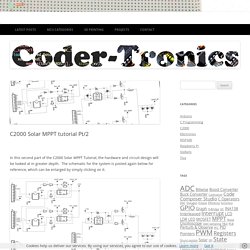
The schematic for the system is posted again below for reference, which can be enlarged by simply clicking on it. Buck Converter Design The first step was to design the buck circuit, this is determined by the output parameters of the system and it’s load. For the first prototype based around the panel purchased for testing, it was decided to aim for a 12V output, therefore a maximum current of 750mA (assuming 10% losses). When calculating a buck circuit the frequency of operation, inductor size and output capacitor size are important, as they determine the current and voltage ripple size. A general rule is the higher the frequency the smaller the inductor and output capacitor size, and a smaller inductor and capacitor size generally lowers the system cost. ΔIL is the inductor ripple current, and in this case a 30% figure was used for the multiplier.
MOSFET Losses. ARDUINO SOLAR CHARGE CONTROLLER ( Version 2.0) Parts: 1.Arduino Nano (Amazon / eBay) 2.P-MOSFET ( Amazon / IRF 9540 x2 ) 3.Power diode ( Amazon / MBR 2045 for 10A and IN5402 for 2A) 4.Buck Converter ( Amazon / eBay) or Voltage Regulator (LM7805) 5.Temperature Sensor( Amazon / LM35)
6V Solar Battery Charger Circuit - Electronic Circuit Projects. In this post we discuss a simple 6V solar battery charger circuit with an automatic cut-off feature using 4 way LED indication, and an overcurrent protection.
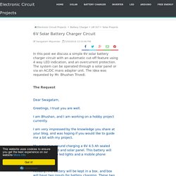
The system can be operated through a solar panel or via an AC/DC mans adapter unit. The idea was requested by Mr. Bhushan Trivedi.The RequestDear Swagatam, Greetings, I trust you are well. I am Bhushan, and I am working on a hobby project currently. I am very impressed by the knowledge you share at your blog, and was hoping if you would like to guide me a bit with my project. My project is around charging a 6V 4.5 Ah sealed battery with grid and solar panel. Actually, the battery will be kept in a box. and box will have two inputs for battery charging. There will not be any automatic switchover. I am attaching a short problem statement along this email for your reference. I am keen to hear from you on this Kind Regards, Bhushan. Solar Panel Charging Rechargeable Batteries. I made a weather station to continuously monitor daylight and temperature.
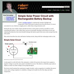
Since the project is placed away from the house, it is more convenient to use a battery to supply power, rather than a long extension cord. Solar Panel Charging Rechargeable Batteries.