
Designing an ESP8266 Sensor Board #1: Prototyping - Open Hardware Labs. The ESP8266 is an amazing WiFi chip that received a lot of attention from the Makers community, for several good reasons.
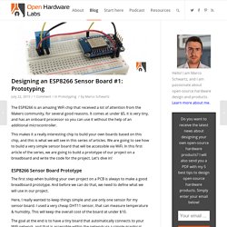
It comes at under $5, it is very tiny, and has an onboard processor so you can use it without the help of an additional microcontroller. This makes it a really interesting chip to build your own boards based on this chip, and this is what we will see in this series of articles. We are going to see how to build a very simple sensor board that will be accessible via WiFi. In this first article of the series, we are going to build a prototype of our project on a breadboard and write the code for the project. Let’s dive in! Control a Relay From Anywhere Using the ESP8266 - Open Home Automation.
As I was building more and more home automation projects using the ESP8266 WiFi chip, I was looking for a simple solution to control my ESP8266 projects remotely.
I wanted to be able to control my projects not only from my local WiFi network, but from anywhere in the world, simply by using a web browser. I found many solutions, but none of them were really suited to my requirements. As you might know, I developed my own library called aREST to control most of the wireless projects I make. Therefore, I decided to modify this library to be able to control projects from outside of a local WiFi network. In this article, I will share those new features of aREST with you, and show you how to control a simple relay from anywhere. Hardware & Software Requirements. Connect the ESP8266 WiFi Chip to your Raspberry Pi - Open Home Automation. In this project, we are going to make a typical home automation project: a WiFi weather measurement station.
We will connect a DHT11 sensor to an ESP8266 board, and access the data via WiFi. However, here, we are actually going to grab that data from a Raspberry Pi, and make the Pi display the data on a simple graphical interface. To do so, we will run a simple web server on the ESP8266 chip. The Raspberry Pi will then access this data via WiFi, and display it graphically. The nice thing is can you can apply this in several other projects, to make the Raspberry Pi the ‘hub’ of your home, with several ESP8266-based devices connected to it. Hardware & Software Requirements For this project, you will of course need an ESP8266 chip.
You will also need a fully configured Raspberry Pi board, with the Raspbian operating system installed on it. You will also need a temperature sensor. This is a list of all the extra components that will be used in this chapter: Hardware Configuration. ESP8266 With Arduino Tutorials. Esp8266 - saving power with NodeMCU's node.dsleep() ESP8266 - On Websockets, mdns, OTA and LEDS. The holiday season is near and that means another project with lots of leds :D (Check Last year E-Hanukkiah.
I haven't used the ESP8266 for the last six months, and was happy to go back using it, discovering many new libraries which were developed during this time. The last few months I've done a lot! Got married, went for a honeymoon for a month and moved to a new house. The last two weeks I could finally relax and go back to my hobbies. I was doing a lot of houseworks since I moved to the new house, so I decided to combine business with pleasure and created a cool atmosphere lights for my living-room.
Here's a video of how it looks like: The project is more than just leds - It is an robust IOT device sitting in my living-room, listening to different requests. In this post I will describe the assembly of this project, but also a lot about the code and problems I encountered on the way. tl;dr for the ADHD readers: Hope you got this far reading the post, here's my code, go and have fun! Esp8266 useful specs. PinMode(), digitalRead(), digitalWrite(), analogWrite() work as usual.
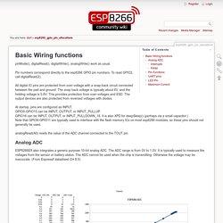
Pin numbers correspond directly to the esp8266 GPIO pin numbers. To read GPIO2, call digitalRead(2); All digital IO pins are protected from over-voltage with a snap-back circuit connected between the pad and ground. The snap back voltage is typically about 6V, and the holding voltage is 5.8V. This provides protection from over-voltages and ESD. At startup, pins are configured as INPUT. AnalogRead(A0) reads the value of the ADC channel connected to the TOUT pin. Analog ADC ESP8266EX also integrates a generic purpose 10-bit analog ADC. Interrupts Pin interrupts are supported through attachInterrupt(), detachInterrupt() functions. AnalogWrite(pin, value) enables software PWM on the given pin. Pin Functions The most usable pin functions are mapped to the macro SPECIAL, so calling pinMode(pin, SPECIAL) will switch that pin to UART RX/TX on pins 1 - 3, HSPI for pins 12-15 and CLK functions for pins 0, 4 and 5.
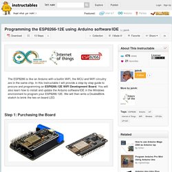
Programming the ESP8266-12E using Arduino software/IDE - All. I bought the NodeMcu Lua ESP8266 ESP-12E + WiFi Motor Drive Expansion Board from a supplier in China.
They arrived within two weeks. Knolleary/pubsubclient.