
Digital Logic Families Part-II. Newest Questions. WEBENCH Design Center. Electronics on Reddit.
Cloud Engineering: Ship faster with better hardware engineering tools - Upverter. Joule Thief. Leaflabs.com. AC Light Dimmer - Andrew Jessop. March 2006 This project came about because a friend of mine had something similar as a component for his final year electronic engineering project.
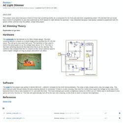
We decided that we would have a kind of competition to see who could build an AVR based AC light dimmer the quickest. I was interested because I had always wanted to experiment with AC power control, and this was the perfect, simple little project. AC Dimming Theory Explanation to go here. Hardware Software. Dms. Electronics. Since my V-USB tutorials became popular, a recurring theme in the comments section have been people who are obviously motivated to try out the tutorial, but due to limited exposure to C language and command-line are either having trouble following my short instructions to compile the example .hex files, or being scared of the command-line, have tried to use AVR Studio instead, and fail.
I have to admit that first I was a bit annoyed by these people – why are they trying to follow a challenging project, when they seemingly have no understanding of how command line, makefiles, C compiler and linking process works? Then, comment by comment, I finally realized that not everyone started coding in the nineties where you launched Windows 3.11 mostly to play Solitaire, and biggest thing in coding productivity was 80×50 text mode which allowed you to have 16-color hacking bliss in your Borland Turbo C++ 3.0 IDE (or RHIDE, after DJGPP came around). HarryLEO 开源硬件.
电子工程师技术之吧-电子博客. Charlieplexing LEDs- The theory. This instructable is less a build you're own project and more a description of the theory of charlieplexing.
It's suitable for people with the basics of electronics, but not complete beginners. Radio software. How to Build a Homemade Clapper to Adjust the Lights and Set the Mood. One night, I was trying to draw a circuit on a chalkboard, but it became too dark to see.
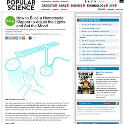
The next day I bought a new lamp, only to find that the board gave off too much glare. I needed a light I could easily adjust. H-Bridge on a Breadboard. Inovix Labz. Power Amplifier. Rutgers DCS HackerSpace. Electronic amplifier. A practical bipolar transistor amplifier circuit There are four basic types of electronic amplifier: the voltage amplifier, the current amplifier, the transconductance amplifier, and the transresistance amplifier.
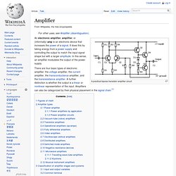
A further distinction is whether the output is a linear or nonlinear representation of the input. Class A Amplifier - Transistor Amplifier Tutorial. The Class-A Amplifier Common emitter amplifiers are the most commonly used type of amplifier as they have a large voltage gain. They are designed to produce a large output voltage swing from a relatively small input signal voltage of only a few millivolt’s and are used mainly as “small signal amplifiers” as we saw in the previous tutorials.
Simple Class-A Power Amplifier - Electronic Circuits and Articles. Class E Transmitters - Theory of Operation. || Class E Home || WA1QIX home page || Class E Forum || AMFone || The idea behind class E is to reduce or eliminate the effects the various capacitances within the MOSFET have on efficiency and operation at high frequencies.
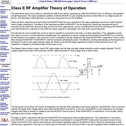
The major operational condition is that the MOSFET is only switched (turned on) when there is no voltage across the device. This eliminates switching losses, a major loss component of most RF amplifiers. There are three capacitances at work within the MOSFET itself; the input capacitance, the output capacitance and the so-called "transfer" (drain to gate) capacitance. Semi Conducting - A Guide. --------------------------------------------------------------------------------------------------------------------------------- Anyway, Electronics, as stated before by many of my comrades around the globe, have all become the most important things in our daily lives.
Cell phones, computers, TV's, keyboards, mice, speakers, everything all uses electricity and of course, SEMICONDUCTORS. You could easily try and open up your phone, or your xbox, and there's hundreds of big, small, tiny, and huge black things lurking inside them. Those things have silicon, among other metals mashed together inside of them. Microcode. Microcode is a layer of hardware-level instructions or data structures involved in the implementation of higher level machine code instructions in central processing units, and in the implementation of the internal logic of many channel controllers, disk controllers, network interface controllers, network processors, graphics processing units, and other hardware.

It resides in special high-speed memory and translates machine instructions into sequences of detailed circuit-level operations. It helps separate the machine instructions from the underlying electronics so that instructions can be designed and altered more freely. It also makes it feasible to build complex multi-step instructions while still reducing the complexity of the electronic circuitry compared to other methods. Writing microcode is often called microprogramming and the microcode in a particular processor implementation is sometimes called a microprogram.
Overview[edit] Swarm robots - XinCheJian. The Goal of Swarm Robots The goal of this project is to BUILD A SWARM OF ROBOTS.
In the process of building these robots, we hope that members who participate will also learn different kinds of skills. Regular Meetup Night. Circuits.io. Tlc5940. TLC 5940 - PWM Driver. Demystifying the TLC5940 - artcfox. A free book/library by Matthew T.
Pandina This book explains how to turn the datasheet and application notes for the TLC5940, a 16 channel LED driver with dot correction and grayscale PWM control, into an unencumbered C library for use with an AVR microcontroller. This library uses the CLKO pin of the AVR to drive the GSCLK line of the TLC5940, which allows grayscale values to be updated at 3906.25 Hz with a CLK I/O of 16 MHz, and 4882.8125 Hz with a CLK I/O of 20 MHz. Transistor–transistor logic. Transistor–transistor logic (TTL) is a class of digital circuits built from bipolar junction transistors (BJT) and resistors. It is called transistor–transistor logic because both the logic gating function (e.g., AND) and the amplifying function are performed by transistors (contrast with RTL and DTL). TTL is notable for being a widespread integrated circuit (IC) family used in many applications such as computers, industrial controls, test equipment and instrumentation, consumer electronics, synthesizers, etc.
The designation TTL is sometimes used to mean TTL-compatible logic levels, even when not associated directly with TTL integrated circuits, for example as a label on the inputs and outputs of electronic instruments.[1] After their introduction in integrated circuit form in 1963 by Sylvania, TTL integrated circuits were manufactured by several semiconductor companies, with the 7400 series by Texas Instruments becoming particularly popular. History[edit] Learn Electronics Online for Free. Video and Podcasts: Events by Category. Welcome to the Website for Digital Integrated Circuits Second Edition Jan M. Sallen-Key Low-pass Filter Design Tool. DIY Resistor Substitution Decade Box ‹‹ Digital Underpants. Post by: Admin On: Aug 18/12 With 36 Comments. » Blog Archive » Capacitance meter (Part 1) Part 1, 2, 3, 4 Identifiying a capacitor is no big deal as long as the labelling is readable: Depending upon the package type, we will use some conversion formula, like:
FilterDesignIn30Seconds.pdf (application/pdf Object) Comparison. CircuitLab - online schematic editor & circuit simulator. Simple Pre-Amp with One Transistor « Audio Circuit. This is a very simple pre-amp circuit which use a transistor as a active component to boost the input signal. Its simplicity makes this circuit easy to built and inexpensive. Condenser Mic preamplifier « Audio Circuit. Make a Simple Audio Amplifier. Tutorials. Successive approximation ADC. Block diagram[edit] Pulse & Digital Circuits - U.a.bakshi. Very simple Arduino capacitance meter using 16 bit timer and analog comparator. IR Short Distance Beam Cut Detector.
12 June 2010. Designing Bipolar Transistor Audio PreAmplifiers. ISD voice recorder IC. Search.
Radio. Hong Kong.