
The Closest Thing to a Map of the Dark Net: Pastebin. The vast majority of hidden service websites (that is, the ones you need Tor to get to) have to walk a fine line.

They want to remain somewhat hidden, but not so hidden that no one can actually find them. Therefore, there is evidence of how to find deep web sites littered all over the public, or "clear" internet. Staffan Truvé, CEO of Recorded Future, a Sweden-based cyber threat research company, has tracked down where users talk about the dark web and direct each other to specific hidden sites in an attempt to visualize what it looks like. In fact, the company is persistently monitoring many parts of the dark web. "Some people are over mystifying the dark web.
"We capture everything that's posted on paste sites" Recorded Future scrapes everything posted on Pastebin and other "paste" sites, which are sites where plaintext can be posted anonymously. "If you're in this business to sell something, well, you need to advertise it somewhere," he said. "We just ignore that content," he said. Home - Arduino Manchester Encoding - Mchr3k.
This is a Manchester encoding RF library which works on Arduino and ATTiny.
Library supports: various microcontrollers ATmega328 ATmega8 ATMega32U4 ATtiny84 (44, 24) ATtiny85 (45, 85) various microcontroller's speed both RX and TX 1Mhz (see notes for TX) 8Mhz 16Mhz 16.5Mhz ATtiny85 various transmission speeds 300baud 600baud 1200baud 2400baud 4800baud 9600baud 19200baud With this library you can sucessfully transmit data between various microcontrollers runnning at various speeds even if their clock speed varies up to 100%. Works great with innacurate internal oscilator. Your maximum transmission speed will depend on many factors like transmitter type, antenna, distance, enviroment noise, microcontroller type and speed. Mchr3k/arduino-libs-manchester. SoftwareSerialPrint. Arduino Serial Communication, Bytes, Bases, and ASCII Characters
Understanding data types is especially important if you wish to use serial communication to send data to your Arduino and have the ATmega328 act on this data.
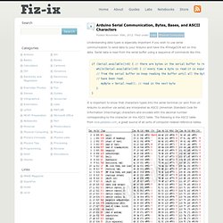
Serial data is read from the serial buffer using a sequence of commands like this. if (Serial.available()>0) { // there are bytes in the serial buffer to read while(Serial.available()>0) { // every time a byte is read it is expunged // from the serial buffer so keep reading the buffer until all the bytes // have been read. myByte = Serial.read(); // read in the next byte } } It is important to know that characters typed into the serial terminal (or sent from on Arduino to another via serial) are interpreted as ASCII (American Standard Code for Information Interchange) characters and encoded with the decimal number corresponding to the character on the ASCII table. The following is the ASCII table from lookuptables.com, a great source of all sorts of computer-related reference tables. Assignment. Print hexa to asc arduino - Google Search.
Arduino RF Communication using RX & TX link Modules. This Tip/Walk-Through will guide you through a simple one way communication link between two Arduinos.
The Project uses these RX/TX Radio Frequency (RF) Link Modules. Edit :- Links updated - old ones where retired .Boooooo. How to use 315Mhz RF transmitter and receiver modules with arduino. Description: This wireless transmitter and receiver pair operate at 315Mhz.
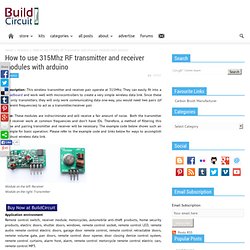
They can easily fit into a breadboard and work well with microcontrollers to create a very simple wireless data link. Since these are only transmitters, they will only work communicating data one-way, you would need two pairs (of different frequencies) to act as a transmitter/receiver pair. Note: These modules are indiscriminate and will receive a fair amount of noise. Both the transmitter and receiver work at common frequencies and don’t have IDs. Therefore, a method of filtering this noise and pairing transmitter and receiver will be necessary. Receiver module parameters 1. 1. RF 315/433 MHz Transmitter-receiver Module and Arduino : Arduino Virtual Wire Library. Fortunately , There is a popular Library for arduino Called "" VirtualWire"" Created by Mike McCauley VirtualWire is an Arduino library that provides features to send short messages, without addressing, retransmit or acknowledgment, a bit like UDP over wireless, using ASK (amplitude shift keying).

Supports a number of inexpensive radio transmitters and receivers. This library allow You to send and receive data"byte" and string easily , First Download the library from Here . after extract the folder, and move it to " Libraries " on the arduino Folder this is a simple code , it will send character '1' and after 2 sec will send character '0' and so on . Módulo Transmissor 433.92 MHZ - Mult Comercial Ltda - Componentes Eletrônicos. Módulo Receptor 433.92 MHZ - Mult Comercial Ltda - Componentes Eletrônicos. Project Info. <virtualwire> library optimization for DigiSpark ... and other arduino. DigiUSB, issue with Echo example. Keyboard example working. Can you try changing the delay(10); line to _delay_ms(30); I'm not the original poster, but I'm having the same problem.
The keyboard example works, but when I load the Echo example, USBProbe doesn't show any communications at all. However, I do see the device on the USB bus, and I can probe info from it using a nodejs program. Here's the nodejs code: var HID = require('node-hid'); var device,ds;var devices = new HID.devices(0x16c0, 0x05df); // look for digisparks if (devices.length > 0) { console.log(devices); console.log('Attaching to first entry.'); device = devices[0]; console.log('USB Path ', device.path); ds = new HID.HID(device.path); ds.write([65, 65, 65, 13, 10]); ds.read(onRead); } else { console.log('No Digispark found.');} ds.read(onRead); }} When I run this, I get the following output:
Digispark:tricks [Digistump Wiki] Here are some neat tricks to do unusual things with your digispark When the digispark boots up, it uses the USB signal to calibrate its clock to 16.5mhz.
![digispark:tricks [Digistump Wiki]](http://cdn.pearltrees.com/s/pic/th/digispark-tricks-digistump-87264937)
When powered by an external power supply this doesn't happen and the clock speed is closer to 16.0mhz, with roughly 10% accuracy. How to get the 433 Mhz RF Modules to work with the attiny85-10pu. @mrburnette- In the specifications the max speed it will run at is 10 Mhz. below i have gone through something i noticed when uploading a simple blinking light sketch.

Will this library that is supposed to run at 8Mhz work for my chip? Sorry for the most likely stupid question, but I am brand new to this stuff. @DorianMcCarthy I have the program i am trying to upload below. The core of the program is from Kevin Darrah on youtube. Digispark + VirtualWire (Solved!) Yep, the symbol (F_CPU) is fixed at compile time.
One thing to look out for is a lot of arduino software does maths which assumes F_CPU will be whole millions, like 16000000 or 8000000. They'll do things like (F_CPU / 1000000UL) to get 16, then use that in timing related math, chopping off the .5 when using the regular digispark core. If you're interested in playing with the clock speed a bit, you can speed up the digispark by incrementing OSCCAL like this: void setup() { OSCCAL += 1;} Then the spark will run a tiny bit quicker after that line.
Virtual wire attiny85 - Google Search. Virtualwire - Google Search. Digispark pin virtualwire - Google Search. VirtualWire on attiny85 - Grupos do Google. Virtual wire and attiny85. HI All,I have a project that has attiny85 send a string via a 433MHZ transmitter and at the moment a arduino nano picks up this with the receiver and tests the string like a password, if correct throws relay. this all works perfect. Im now wanting to replace the arduino nano with an attiny85 like i did with the transmitter, however there seems to be an issue, the code will no longer compile for board selected attiny85, if i change the board back it compiles fine.... weird here is the code, I have replaced the string with # for reasons of my own choosing #include <VirtualWire.h>
Attiny - RF remote control using VirtualWire on ATtiny85 running at 8MHz on internal oscillator - Arduino Stack Exchange. I'm trying to make an RF remote control using ATtiny85 running at 8MHz on internal oscillator, this cheap RF 434MHz transmitter module (like the one below), and VirtualWire lib, but had no success so far. So, before I go any further, is it possible to use VirtualWire with ATtiny85 running at 3.6V and 8MHz with its internal oscillator? If so, how? I've found a few scattered sources of information on the Net about it, but couldn't make much sense of it.
Cosa/examples/Wireless/CosaWirelessButton/CosaWirelessButton.ino at master · mikaelpatel/Cosa. Cosa. DigisparkArduinoIntegration/libraries/DigisparkVirtualWire/examples at master · digistump/DigisparkArduinoIntegration. DigisparkArduinoIntegration/libraries/DigisparkVirtualWire/VirtualWire.h at master · digistump/DigisparkArduinoIntegration. Attiny 85 virtualwire - Google Search.