
View forum - Bare metal. FAQ Register Login Bare metal Post a new topic 545 topics Page 1 of 22 1, 2, 3, 4, 5 ... 22 Forum Replies Views Author Last post Return to Board index Sorting Options.
Lab5 bootloader - logicworldzju的专栏. David Welch的GitHub的 bootloader05给出了一个非常简单的RPi bootloader,他的代码链接在内存的0x00020000位置,一直在监听串口是 否有XMODEM协议的文件下载,如果有就开始接收数据,并复制到0x00008000位置,传输完成后跳转到 0x00008000去执行。
TA写了一个Python脚本,按照下面的命令调用脚本可以下载并执行用户程序python xmodem-loader.py -p com3 -baud 115200 output.bin你的任务是修改bootloader和python脚本实现如下功能:调用命令 python xmodem-loader.py -p com3 -baud 115200 启动脚本并且与板卡建立串口连接,之后可以发送下面的命令。 Load *.bin 下载程序*.bin go 执行已下载的程序 peek addr 以一个字为单位读取内存中addr位置的数据(addr是4字节对齐,十六进行的形式,长度为8,例如 0x00008000),并以十六进制的形式输出 poke addr data 以一个字为单位修改内存中addr位置的数据为data(addr是4字节对齐,十六进行的形式,长 度为8, data也是十六进行的形式,长度为8) verify *.bin 验证已下载的程序和*.bin是否完全相同。 树莓派的板子。 SD卡(已经有镜像刷入)。 电源线及USB充电器。 此处有必要先来讲讲原理性问题。 树莓派的启动: 下面是来自David Welch的github中的关于树莓派启动的介绍。 所以,此处的bootloader,其实就是kernel.img。 树莓派的内存结构图: Dwelch67/raspberrypi. Setting up LIRC on the RaspberryPi - alexba.in. June 8th 2013 Update: I have completed a soldered circuit prototype, complete with a full parts list and high resolution build pictures.
Please read Open Source Universal Remote - Parts & Picturse to learn more. March 9th 2013 Update: I have formalized the schematic and parts list that I’m using and have made it available on Upverter. Please read RaspberryPi IR Schematic for LIRC for more details. Raspberry Pi Serial Communication: What, Why, and a Touch of How « Jeff's Skinner Box.
I started exploring how to get a LCD display operational with a Raspberry Pi (RPi).

I checked out two hardware configurations: the bare bone LCD 16×2 display driven by the HD44780 chip set, which takes 6 wires to operate, and another configuration that uses a Adafruit shield that requires only 2 wires. It quickly became clear to me that I knew very little about how the LCD display works (maybe not an important topic for me) and I didn’t fully understands the RPi’s serial communications capabilities (something I must fully understand). Adafruit does give some nice tutorial that provide instructions on how to get both configurations work on the RPi, but I don’t like blindly follow tutorials without having a deeper understanding of my options and the underlining hardware.
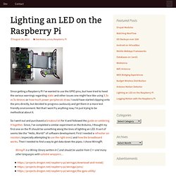
So what are the serial communication options supported by the Raspberry Pi, under what situations would you use them, and how do you use them? Raspberry Pi and the Serial Port. Cheat Sheet - Physical Computing with Raspberry Pi. Basic GPIO Access Setup Raspberry Pi GPIO pin layout.
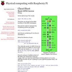
Diagram from eLinux. Raspberry-gpio-python - Python library for GPIO access on a Raspberry Pi. Lighting an LED on the Raspberry Pi. Since getting a Raspberry Pi I’ve wanted to use the GPIO pins, but have tried to heed the various warnings regarding static and other issues one might face like using 3.3v vs 5v devices or how much power peripherals draw.
I could have started clipping onto the pins directly, but decided to progress cautiously and get them in a more test friendly environment. Not that I wont fry anything now, I’m just trying to be methodical about it. So I went out and purchased a breakout kit for it and followed the guide on soldering it together. Since, I’ve completed a similar experiment on the Arduino, I thought my first one on the Pi should be something along the lines of lighting an LED. It sort of seems like the “Hello, World!” WiringPi is a Wiring library written in C and should be usable from C++ and many other languages with suitable wrappers… Raspberry Pi I2C (Python) Control Stuff with your Raspberry Pi (GPIO) over the internet. Raspberry Pi. Update: 14th May, 2013 wiringPi version 2 has been released and now has its own website ( to look after it.

Most of the documentation on the projects site has been copied over to it the new site, but there may still be 1 or 2 pages that are still missing. I’d encourage you to use the new site if possible where there will be a forum and wiki. The following tables give the mapping of the Raspberry Pi GPIO Pins to the GPIO connector in relation to the pin numbers and the physical location on the connector.
This is a representation of the GPIO connector as viewed looking at the board from above, with the USB power at the top and the GPIO to the top-right of the board. If using the connector pin numbering, then note that Pin 1 on the connector is the 3.3v supply. Using the GPIO. Control Raspi GPIO pins in the browser. WebIOPi : control your Pi’s GPIO with a browser ! WebI0Pi 0.6 has been released, click here for details.

I’m proud to present my new project, WebIOPi. This is a web application which allows you to control your Raspberry Pi’s GPIO. Just install it on your Pi, and use any browser from your network. It’s useful to start enjoying GPIOs and also to debug some circuits without writing any line of code. It also allows to control your Pi’s GPIOs over Internet, so it’s a good starting point for home remote control. You can even fully customize the included UI with few CSS modifications or use the REST API to build your own WebApp. Under Apache License, full doc, code, packages and examples are available on the Google Code project page. Features Supports binary GPIOs, in both input and output.HTML / Javascript / CSS client sideEasily customize UIREST/JSON Web APIServer side available in several technologies PHP/ApachePHP/lighttpdPythonSmartphone compatibleAuto-refresh. Raspberry Pi and GPIO Permissions. It works!
Okay, back up a little. Getting a PHP web interface to talk to hardware proved to be rather difficult. You need root access to control hardware but the web service runs with minimal permissions. So how does one bridge the gap without compromising the system?