
According to Pete 10-2-11: 555 Timers. Monostable or "One Shot" or Pulse Extender Circuit. When the circuit is turned on, the output is LOW and a brief negative pulse on pin 2 will make the output go HIGH for a period of time determined by the value of R and C.
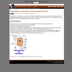
If pin 2 is low for longer than this period, the output will remain HIGH while pin 2 is LOW and immediately go LOW when pin 2 goes HIGH. When the circuit is turned on, the capacitor is uncharged. Pin 6 sees a LOW and pin 2 sees a HIGH. Remember: Pin 2 must be LOW to make the output HIGH. Pin 6 must be HIGH to make the output LOW. Adventures in Arduino. APC (Atari Punk Console) PWM using 555 timer. PWM using 555 timer audioguru: Darrin,The 3.4V is the reference output voltage of the other chip which is being used to power the 555.
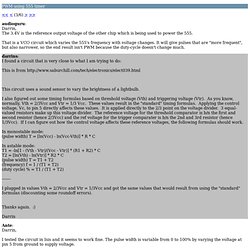
That is a VCO circuit which varies the 555's frequency with voltage changes. It will give pulses that are "more frequent", but also narrower, so the end result isn't PWM because the duty-cycle doesn't change much. darrins: I found a circuit that is very close to what I am trying to do: Atari Punk~Stepped Tone Generator. I have got round this problem by having a fixed charge on C3 through a 680k resistor (R3) which on its own produces a large pulse-width, to have control over the pulse-width i have used the voltage control pin 11.
The voltage control pin affects the internal reference voltage of the timer. R6 (10k) and Q1 -pnp transistor apply a bias voltage to the voltage control pin VR2 (which is now a log pot) is connected to ground at 0ohms resistance the pulse output is at it shortest (divides the astable input frequency by 1) and its current consumption is 1.5mA. When VR2 is at maximum resistance the pulse-width is at its longest and the current consumption drops to 0.5mA (tested on a bread board)
555osc_mod.pdf (application/pdf Object) The_555_timer_revised.pdf (application/pdf Object) Ch16.pdf (application/pdf Object) 555 Siren Generator - EduTek Ltd - Electronic Projects. 555 Timer IC-Block Diagram-Working-Pin Out Configuration-Data Sheet. A complete basic tutorial of 555 Timer IC.
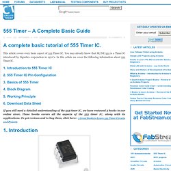
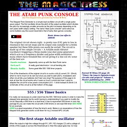
This article covers every basic aspect of 555 Timer IC. You may already know that SE/NE 555 is a Timer IC introduced by Signetics corporation in 1970′s. In this article we cover the following information about 555 Timer IC. 1. Siren Circuits free electronic circuit links. February 2001 Project. February 2001 Project : Assortment of Siren Circuits This month I am making 3 different types of siren circuits based on the 555 timer.
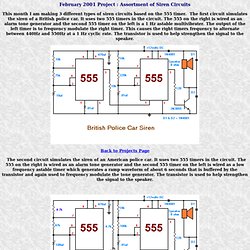
The first circuit simulates the siren of a British police car. It uses two 555 timers in the circuit. 555 Timer Tutorial (Monostable Multivibrator) The 555 Timer We have seen that Multivibrators and CMOS Oscillators can be easily constructed from discrete components to produce relaxation oscillators for generating basic square wave output waveforms.
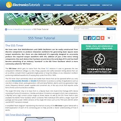
But there are also dedicated IC’s especially designed to accurately produce the required output waveform with the addition of just a few extra timing components. One such device that has been around since the early days of IC’s and has itself become something of an industry “standard” is the 555 Timer Oscillator which is more commonly called the “555 Timer”. The 555 timer which gets its name from the three 5kΩ resistors it uses to generate the two comparators reference voltage, is a very cheap, popular and useful precision timing device that can act as either a simple timer to generate single pulses or long time delays, or as a relaxation oscillator producing stabilized waveforms of varying duty cycles from 50 to 100%.
555 Timer Circuits and Other DIY Circuits Projects. CookBook Entries. 555 Timer Circuits. SCAP: Astable (555 timer) Astable multivibration circuit using 555 timer Operation of this circuit base on charging and discharging of a capacitor via a resistor.
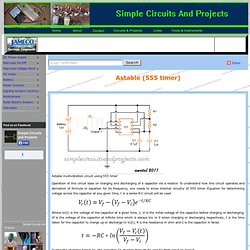
To understand how this circuit operates and derivation of formula or equation for its frequency, one needs to know internal circuitry of 555 timer. Colour Shifting For Bi-Colour LED's. These circuits provide a means of altering the YELLOW output of RED / GREEN type two colour light emitting diodes.
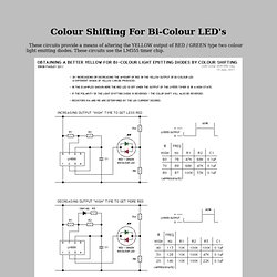
These circuits use the LM555 timer chip. Bi-Colour LED Output Shifting Schematic Bi-Colour LED Output Shifting Go back to the Pageless Circuits List Return to the Main Page The explanations for the circuits on these pages cannot hope to cover every situation on every layout. If you use any of these circuit ideas, ask your parts supplier for a copy of the manufacturers data sheets for any components that you have not used before. Although the circuits are functional the pages are not meant to be full descriptions of each circuit but rather as guides for adapting them for use by others. 555 astable calculator. LM555 Timer Circuits. 11206.doc. 555 Astable Circuit. 555 Timer Calculator. This page helps you calculate figure out the timing of a 555-based astable timer.
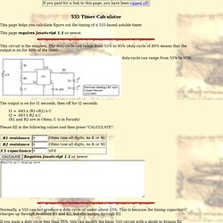
This page requires JavaScript 1.1 or newer. This circuit is the simplest. The duty-cycle can range from 55% to 95% (duty-cycle of 80% means that the output is on for 80% of the time). duty-cycle can range from 55% to 95% The output is on for t1 seconds, then off for t2 seconds. t1 = .693 x (R1+R2) x C t2 = .693 x R2 x C (R1 and R2 are in Ohms; C is in Farads) Please fill in the following values and then press "CALCULATE". HVLabs.com. 555 Based Simple Servo Controller Servos are very useful devices for a number of projects, such as robotics, automation or just remotely controlling something, eg model car steering.
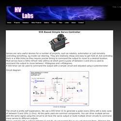
They are relatively cheap and easy to get hold of, but controlling them is a little tricky as they requrie precise timing to command the output to move to a desired location. Most servos have a 50Hz refresh rate (20ms) at which point a pulse of between 1 and 2ms is used to command the output to move between -45degrees and +45degrees. 555 and 556 Timer Circuits. Tutorial 5: 555 LED Flasher. Created on: 31 July 2012 A 555 (triple five) timer IC (integrated circuit) is used in this tutorial to flash an LED on and off. The video below shows the circuit in action: In this tutorial you will learn: About integrated circuits (ICs) More about circuit diagrams. Prerequisites Complete tutorial 2 and read about integrated circuits. 555 timer. 555 Timer Navigation Custom Search Learn about the 555 by building the DOCTRONICS Safety Lights Project: 1.
50 - 555 Circuits. Save 50 - 555 Circuits (more than 101 Circuits) as: .doc (2.4MB) or .pdf (1.6MB) (16-10-2012)(This eBook is being updated all the time and the .doc and .pdf will NOT contain the latest additions) For our other free eBooks, Go to: 1 - 100 Transistor Circuits Go to: 101 - 200 Transistor Circuits Go to: 100 IC Circuits. The 555 Precision Timer IC. Learn about the useful and inexpensive 555 timer IC in this detailed tutorial! Hello readers Today we revisit one of the most popular integrated circuits ever conceived – the 555 timer IC.
“Triple-five”, “five-five-five”, “triple-nickel” … call it what you will, it has been around for thirty-eight years. 47 projects to do with a 555! 555 Timer Projects. 555 Timer Program for Windows. ** Works with all versions of Windows ** This program allows you to calculate Resistor and Capacitor valuesfor both Astable and Monostable modes.
Screenshot. Basic 555 timer Arduino project. I put together the arduino protoshield from sparkfun. Excellent instructions at atomicsalad. Even though it’s a standard through-hole kit, atomicsalad’s instructions were nice to follow along. After it was put together I had a few built-in LED lights to play with. Tutorial 13: Wailing Siren. Created on: 4 August 2012 In this tutorial you will build a wailing siren that plays a tone that increases and decreases in pitch.