
Minuteur Timer longue durée à PIC 16F84A / 16F628A. Projet à microcontrôleur PIC 16F84A / 16F628A Minuteur longue durée 1.
Version 5 digits 1.1. Cédric // PiOnPiOn » Minuterie à PIC 16f84 pour insoleuse. Voici une minuterie pour votre insoleuse (ou autre) gérée par un pic 16F84, possibilité de réglage du compte à rebours de 5s en 5s, pause avec reprise, commande directe du 220V, alimentation par un tension de 0 à 20Vcc. tout ce qu’il faut pour la réaliser se trouve dans cette archive: MinuteriePIC.zip Suite à une erreur dans le schéma placé dans l’archives, voilà la version corrigée ci desssous (cliquez pour agrandir):

Minuterie pour Insoleuse LED UV II. La version deux, de l'insoleuse à LED UV, est en bonne voie.
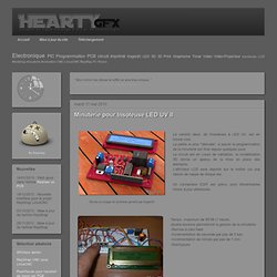
La partie la plus "délicate", à savoir la programmation de la minuterie est finie depuis quelques jours Le circuit est en cours de validation, la modélisation 3D donne un aperçu de la mise en place des éléments. L'afficheur LCD sera déporté sur le boitier via une liaison de nappe de disque dur. Insoleuse LED UV. Rotary encoder with arduino - krishmindmesh. Hello there...

A few weeks ago I ordered a couple of positive photosensitive boards from element14 and received them in course of time.My next issue to address was UV exposure unit for exposing the photosensitive pcb. As with any full-time electronic engineer/part-time hobbyist worth his salt i set out to build one myself. The basic specs/requirements are :- PCB Photographic Artwork Transfer UV Cabinet. I also have made one UV Cabinet but i use an hexagonal pattern in the Led distribution and Works great.

One question, in the new version with 12w per side do you use Led's with more power or reduce the distance between the Led's? Best Regards, Fernando. That specific task of higher quality of production cannot be done easily IMHO only by experimenting, but it has to be supported with practical mathematics/physics. I am in the middle of calculations and believe that something will come up from those. I have a suggestion: before you decide to fix the distance between LEDs or to fix the distance between the LEDs and PCB, just drop me a note, maybe at that time I shell come up with some special values to suggest them for your (and mine) construction. The exposure time is typically 9 minutes (540 sec). Very nice project indeed. Again all congratulations to the idea, especially plexiglass diffuser! 0-9999 seconds count down timer using PIC12F683 microcontroller. The goal of this project is to construct a simple 0-9999 seconds count down timer with an alarm and a display.
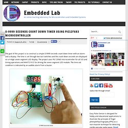
The time is set through two tact switches and the count down seconds are displayed on a 4-digit seven segment LED display. The project uses PIC12F683 microcontroller for all I/O and timing operations and MAX7219 IC for driving the seven segment LED module. The time out condition is indicated by an audible alarm from a buzzer. 0-9999 seconds timer Circuit diagram The complete circuit diagram of this project is shown below. Candrian Haris Andrianakis » Switch Timer V2.0. After some modifications on my UV exposure box (scanner) for better UV expose, i desided that a better pcb must me designed for switch timer.
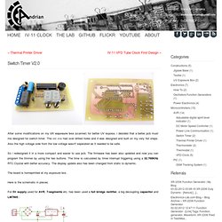
The old one had over drilled holes and it was designed and built on my very fist steps. Also the high voltage side from the low voltage wasn't seperated as it needed to be safe. So i redesigned it in a more compact and easier to use pcb. The firmware has been also updated and now you can program the timmer by using the two buttons. Arc's Lab » Blog Archive » PIC Countdown Timer. This project is intended as a countdown timer for a UV exposure box for PCB development that uses fluorescent UV lamps (it will also work with any other lamp, don’t worry).

It is based around a PIC16F627 micro and has following features: Brendon Archibald's Psychoanalytical (restarting countdown) Timer. Psychoanalytical (restarting countdown) Timer by Brendon Archibald [websales optusnet.com.au] Source Code for 16F648A (Verified) Source Code for 16F628A (Verified) The purpose of this project was to create a five minute timer that beeps and restarts when it reaches zero.
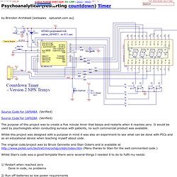
It would be used by psychologists when conducting surveys with patients, no such commercial product was available. Whilst this project was designed with a purpose in mind it was also an experiment to see what can be done with PICs and as an educational device when teaching myself about code. The original code/project was by Bruce Gennette and Stan Ockers and is available at (Many thanks to Stan for the well commented code.) Count down timer for UV PCB exposure boxes - New Project - UNREGISTERED VERSION. Le site d'Aurélien : Electronique, CASIO, Outils Web, etc... David Tait's PIC Archive. David Tait's PIC Archive (This is a local copy.
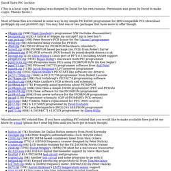
The original was dumped by David for his own reasons. Permission was given by David to make copys. Thanks David.) Most of these files are related in some way to my simple PIC16C84 programmer for IBM compatible PCs (download pic84pgm.zip and pic84v05.zip). 84pgm.zip (30K) Nigel Goodwin's programmer S/W (includes disassembler) bestpp84.zip (62K) A hybrid of 84pgm.zip and pp87.zip (a best buy?) Miscellaneous PIC related files. Last changed and HTML 2.0 checked : 19 March 1999. PIC Countdown Timer. Back PIC Countdown Timer Based on the April '99 project of Stan Ockers (ockers@anl.gov ), available on David Tait's archive page. Thanks Stan! And on the modified version by Aurelien (aurelienr@hotmail.com ). Thanks Aurelien! Description : The purpose of this timer is to provide a countdown time from 1 second to 99 minutes & 59 seconds.
The Power Supply Unit (PSU) schematic is simple and straight : The 2x9VAC from a 3VA transformer is rectified by diode D5 & D6 and smoothed by C11 & C12 to obtain about 12VDC voltage. The main schematic : The main part in the schematic is of course the PIC16F84. The lower nibble of PORTA is used to drive the 4543 'BCD to 7-segment driver/decoder', the lower nibble of PORTB to drive the 7-segment digits through transistors T1 to T4. Three push buttons allow for user input: S1 - START/STOP push button: Starts the actual displayed count down time, or interrupts (stops) the countdown in progress.
A 50ms beep from the buzzer confirms every key press.