
Gliffy.com - Create and share diagrams online. UML state machine. UML state machine,[1] also known as UML statechart, is a significantly enhanced realization of the mathematical concept of a finite automaton in computer science applications as expressed in the Unified Modeling Language (UML) notation.
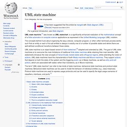
The concepts behind it are about organizing the way a device, computer program, or other (often technical) process works such that an entity or each of its sub-entities is always in exactly one of a number of possible states and where there are well-defined conditional transitions between these states. UML state machine is an object-based variant of Harel statechart,[2] adapted and extended by UML.
The goal of UML state machines is to overcome the main limitations of traditional finite-state machines while retaining their main benefits. UML statecharts introduce the new concepts of hierarchically nested states and orthogonal regions, while extending the notion of actions. Basic state machine concepts[edit] Open Solution Company: UML for Eclipse and BPMN designer. Activity diagram.
Activity diagrams are graphical representations of workflows of stepwise activities and actions[1] with support for choice, iteration and concurrency.
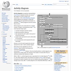
In the Unified Modeling Language, activity diagrams are intended to model both computational and organisational processes (i.e. workflows).[2][3] Activity diagrams show the overall flow of control. Activity diagrams are constructed from a limited number of shapes, connected with arrows.[4] The most important shape types: rounded rectangles represent actions;diamonds represent decisions;bars represent the start (split) or end (join) of concurrent activities;a black circle represents the start (initial state) of the workflow;an encircled black circle represents the end (final state). Arrows run from the start towards the end and represent the order in which activities happen. Hence they can be regarded as a form of flowchart. See also[edit] References[edit] Jump up ^ Glossary of Key Terms at McGraw-hill.com.
External links[edit] Object Management Group - UML. Unified Modeling Language. UML logo The Unified Modeling Language (UML) is a general-purpose modeling language in the field of software engineering, which is designed to provide a standard way to visualize the design of a system.[1] It was created and developed by Grady Booch, Ivar Jacobson and James Rumbaugh at Rational Software in the 1990s.[2] In 1997 it was adopted by the Object Management Group (OMG), and has been managed by this organization ever since.
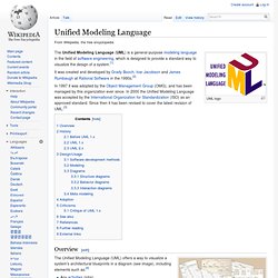
In 2000 the Unified Modeling Language was accepted by the International Organization for Standardization (ISO) as an approved standard. Since then it has been revised to cover the latest revision of UML.[3] Overview[edit] A collage of UML diagrams. The Unified Modeling Language (UML) offers a way to visualize a system's architectural blueprints in a diagram (see image), including elements such as:[4] History[edit] History of object-oriented methods and notation. Before UML 1.x[edit] UML 1.x[edit] UML 2.x[edit] There are four parts to the UML 2.x specification: Sequence diagram. Sequence diagram of e-mail message sequence A sequence diagram is an interaction diagram that shows how processes operate with one another and in what order.
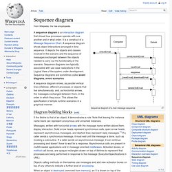
It is a construct of a Message Sequence Chart. A sequence diagram shows object interactions arranged in time sequence. It depicts the objects and classes involved in the scenario and the sequence of messages exchanged between the objects needed to carry out the functionality of the scenario. Sequence diagrams are typically associated with use case realizations in the Logical View of the system under development. A sequence diagram shows, as parallel vertical lines (lifelines), different processes or objects that live simultaneously, and, as horizontal arrows, the messages exchanged between them, in the order in which they occur.
Diagram building blocks[edit] If the lifeline is that of an object, it demonstrates a role. UML has introduced significant improvements to the capabilities of sequence diagrams. References[edit] The UML.