
LED Nametag. ME170C/ECE181C Course Webpage. Meets: Tuesday, Thursday 5:30-6:45PM, Engineering II 2163 Course Description Overview of robot control technology from open-loop manipulators and sensing systems, to single-joint servovalves and servomotors, to integrated adaptive force and position control using feedback from machine vision and touch sensing systems.
Design emphasis on accurate tracking accomplished with minimal algorithm complexity. Instructor: Casey Hare Email:casey@engineering.ucsb.edu TAs: Chris Hammetter, cih@engineering.ucsb.edu OH: MWF 3-5, TTh 5-7 Michael Nip, mdnip@engineering.ucsb.edu OH: MW 5-8, TTh 2-4 & 5-8, F 1-4 Announcements 2/10 - Rules for the Final Robot Competition have been added. This website is currently maintained by Michael Nip. Vibrobots. Line Following Robot Tutorials - How To Build, Programming Code and Resources. A line follower robot is a robot able to detect and track a line even if the path is altered by changing the shape of the line.

Usually, this robotic application is intended to be a popular choice for beginners, which can use it for fun or to improve the electronics and programming skills. You can choose to build a simple line follower robot that can track a black line, a white line, or even a sophisticated robot engineered to make the distinction between different colors and able to follow only one color. Regardless of your choice, all of these robots have something in common. These intelligent bots have to move using wheels or tracks, for tracking and detection use sensors, the chassis is the backbone of the robot, a prototyping board is the ‘brain’ of the system, two or more electric motors that produce motion, and any other accessories that can be attached to the robot and improve its performances. CircuitLab - online schematic editor & circuit simulator.
Free Online Schematic Drawing Tool.
Control your servo using a 555 timer!!!!!!!!!!!!!!!!!!!!!!!!!! Francisco Gallego. LEY DE OHM: Electricidad. Simuladores de circuitos eléctricos y electrónicos en línea. Para el aprendizaje de la electricidad y la electrónica, hoy en día resulta imprescindible la utilización de simuladores por ordenador, que nos permiten realizar nuestros diseños y nos muestran el funcionamiento de los circuitos de forma virtual antes de su montaje con componentes reales.
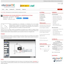
Son muchos los simuladores de escritorio que se utilizan en distintos niveles educativos, pero en este artículo nos centraremos en los simuladores en línea, cuya principal ventaja es que podemos utilizarlos desde cualquier plataforma, pues se ejecutan a través de un navegador web. CircuitLab Es una aplicación muy reciente y ya está recibiendo muy buenas críticas por su sencillez de uso. Permite diseñar muchos tipos de circuitos analógicos y digitales, simularlos, realizar cálculos, guardar los diseños y compartirlos con la comunidad.
Logic.ly Es un simulador de circuitos digitales que tiene dos versiones, una de pago para instalar y otra online. The Logic Lab. Apoyo educativo, interactivo y animado para ser vistos en clase o en casa para las ciencias. Osciloscopio. Multímetro, intensida. Contenido ¿Qué es un circuito eléctrico?
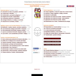
The Basics - Very Basic Circuits. This column is intended to be a place to find really basic information on subjects related to robotics and electronics.
If you have questions about the basics on these subjects, this column is for you. I invite you to submit questions or information to this column. Send me some mail. Kevin Ross The Pull-up Resistor This time in Very Basic Circuits, I would like to talk about pull-up resistors. The Current Limiting Resistor If you have just read the above article, you hopefully understand how a resistor limits the amount of current that can flow through a circuit. There are times when you connect the output of a gate to a device that isn't the input of another device. An important consideration when connecting anything to an output gate is what will happen when the gate drops to logic zero. Most logic parts are capable of handling around 20mA of current per pin. CircuitLab - online schematic editor & circuit simulator. Los Sensores. Ley de Ohm. Animaciones de Física.
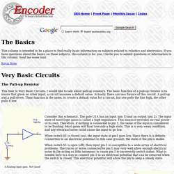
Nuevas Simulaciones - Simulaciones PhET. A Simple and Cheap Dark-Detecting LED Circuit. Here’s a simple problem: “How do you make an LED turn on when it gets dark?”
You might call it the “nightlight problem,” but the same sort of question comes up in a lot of familiar situations– emergency lights, street lights, silly computer keyboard backlights, and the list goes on. Solutions? Lots. The time-honored tradition is to use a circuit with a CdS photoresistor, sometimes called a photocell or LDR, for “light-dependent resistor.” (Circuit Example 1, Example 2.) In this article we show how to build a very simple– perhaps even the simplest– darkness-activated LED circuit.
What can you do with such an inexpensive light-controlled LED circuit? Here are our components: On top: a CR2032 lithium coin cell (3 V). The LTR-4206E is a phototransistor in a 3mm black package. Our starting point is the simplest LED circuit: that of the LED throwie, which has an LED driven directly from a 3V lithium coin cell. The circuit diagram looks like this; please ignore the messy handwriting. ;) Computer Simulations in Physics.