
Winsock Programmer’s FAQ: Winsock Programmer's FAQ. TCP/IP .NET Sockets FAQ. This is an attempt to address some TCP/IP frequently asked questions and present best practices.
While the WinSock Programmer’s FAQ will remain the ultimate FAQ for native code, there is a growing need for a simplified version that addresses the managed interface to TCP/IP sockets. Section 1 - Application Protocol Design 1.1 - Message framing, also known as: “One side sent X bytes, but the other side only got Y bytes.” “One side sent several packets, but the other side only got one packet, which was all the sent packets appended together.” “I need the function that will send exactly one packet of data.” 1.2 - Detection of half-open (dropped) connections, also known as: “My socket doesn’t detect a lost connection; it just sits there forever waiting for more data to arrive.” 1.3 - Application Protocol Specifications 1.4 - XML over TCP/IP Section 2 - Socket Class 2.1 - Socket operations 2.2 - Error handling 2.3 - Using Socket as a client socket 2.4 - Using Socket as a server (listening) socket.
INFO: UDP Datagram Can Be Silently Discarded if Larger than MTU. When a UDP datagram is larger than the MTU size of physical media and there is no ARP entry for the host it is sent to, Microsoft Windows TCP/IP implementation keeps only the last fragment of the UDP datagram sent to a given destination while waiting for an ARP reply.
The rest of fragments are silently discarded. For example, when a WinSock application attempts to send a single UDP datagram with 12501 bytes of data, the IP layer performs fragmentation and generates nine IP fragments on an Ethernet. The first eight fragments are discarded and only the last fragment is kept while waiting for an ARP reply. When the first ARP reply is received, only the last fragment is sent. This behavior is by design and complies to Host Requirement RFC stating that ARP should save at least one packet. To avoid the UDP packet drop: Send a smaller IP datagram than the MTU size before sending a large UDP datagram. For more information about the ARP cache life, refer to the following article: S Guide to Network Programming.
OSI model. The Open Systems Interconnection model (OSI Model) is a conceptual model that characterizes and standardizes the communication functions of a telecommunication or computing system without regard of their underlying internal structure and technology.
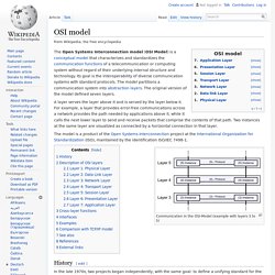
Its goal is the interoperability of diverse communication systems with standard protocols. The model partitions a communication system into abstraction layers. The original version of the model defined seven layers. A layer serves the layer above it and is served by the layer below it. For example, a layer that provides error-free communications across a network provides the path needed by applications above it, while it calls the next lower layer to send and receive packets that comprise the contents of that path.
Ethernet, Ethernet Card,Ethernet and the OSI Model,TCP/IP and the OSI Model,Ethernet Network Topology,Cabling and Cable Lengths, A Chronology of Ethernet. Ethernet is the most common network, supported by many protocols and its low cost.
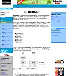
Originally developed by Intel, Digital (now Compaq), and Xerox, it is an open network standard (IEEE 802.3). The Open Systems Interconnect (OSI), established in 1984 by the ISO (International Standards Organization), divides network functions into seven layers: Physical, Data Link, Network, Transport, Session, Presentation and Application Protocol. Application Presentation Session Transport Data Link Network Physical TCP/IP protocol on Ethernet provides all seven layers of the OSI model.Ethernet provides these layers of the OSI (Open SystemsInterconnect) model.
Figure 1. Twisted pair. Twisted pair cabling is a type of wiring in which two conductors of a single circuit are twisted together for the purposes of canceling out electromagnetic interference (EMI) from external sources; for instance, electromagnetic radiation from unshielded twisted pair (UTP) cables, and crosstalk between neighboring pairs.
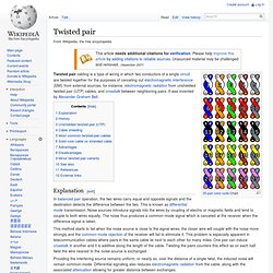
It was invented by Alexander Graham Bell. Explanation[edit] In balanced pair operation, the two wires carry equal and opposite signals and the destination detects the difference between the two. This is known as differential mode transmission. Noise sources introduce signals into the wires by coupling of electric or magnetic fields and tend to couple to both wires equally. This method starts to fail when the noise source is close to the signal wires; the closer wire will couple with the noise more strongly and the common-mode rejection of the receiver will fail to eliminate it. History[edit] Wire transposition on top of pole.