
Debugging a program on the stellaris launchpad board. OpenOCD now supports TI’s stellaris launchpad.
Patching it it’s no longer necessary! The source it’s available here! Getting Started with the Stellaris EK-LM4F120XL LaunchPad Workshop. This workshop has been upgraded to the new Tiva TM4C123G LaunchPad Workshop located here.
No further changes will be made to this page as of 14May2013. Version 1.10 March 2013 Labs are based on CCS 5.3 Introduction. Utzig/lm4tools. Programming the Stellaris Launchpad with GNU/Linux. [Subscribe to the Recursive Labs email Newsletter to get updates][Find out more about our online courses] [Connect with us on Twitter][Facebook Page]
Welcome to the AGehringer.com. UBW (USB Bit Whacker) Project. PIC microcontroller blinking LED without cheating. To change our opcodes to hex file format we need to (1) pad to 8-bit boundary, (2) convert to hexadecimal, (3) change the byte endian and (4) consider where to put our program.
We have explained most of these changes in the previous section The configuration words. Open Vision Control. Billiard ball computer. A billiard-ball computer, also known as a conservative logic circuit, is an idealized model of a reversible mechanical computer based on Newtonian dynamics, proposed in 1982 by Edward Fredkin and Tommaso Toffoli.[1] Instead of using electronic signals like a conventional computer, it relies on the motion of spherical billiard balls in a friction-free environment made of buffers against which the balls bounce perfectly.
Professor Quibb. Documents to Get Started with the TI-Nspire - TI-Nspire Group Website. Main Page - Hackspire. Ralink/Realtek Wireless Dongle (rt3070) on the Raspberry Pi. Realtek WiFi dongle Scenario You have a HAWKING HWUN3 Hi-Gain Wireless Adapter dongle that you want to use on your Raspberry Pi running debian.
Note: the same set of steps will probably work for other variations of Ralink/Realtek wifi dongles [rt2561,rt2661,rt2860,rt2870,rt3070,rt3071,rt3090]. Chrishulbert/friendly_launchpad. Projects. ChipKIT Challenge. So, we have finally finished our entry, a few hours before the deadline!
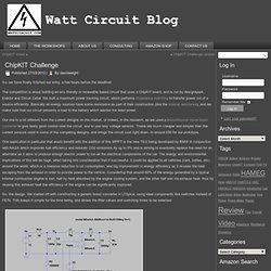
The competition is about building an eco friendly or renewable based circuit that uses a ChipKIT board, and is run by designspark, Elektor and Circuit Cellar. We built a maximum power tracking circuit, which performs impedance matching to transfer power out of a source efficiently. Basically all energy sources have some resistance as part of their construction (like the internal resistance), and we make sure that our circuit presents a load to the battery which wastes the least power. Our one is a bit different from the current designs on the market, or indeed, in the research, as we used a discontinuous mode boost converter to give really good control over the circuit, and to use only voltage sensors.
Embedded Engineering and Programming Information. Grumpy Old Programmer. SecretsOfArduinoPWM. Learning Examples | Foundations | Hacking | Links Secrets of Arduino PWM by Ken Shirriffwith further editing by Paul Badgerthe original document Pulse-width modulation (PWM) can be implemented on the Arduino in several ways.
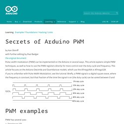
This article explains simple PWM techniques, as well as how to use the PWM registers directly for more control over the duty cycle and frequency. This article focuses on the Arduino Diecimila and Duemilanove models, which use the ATmega168 or ATmega328. If you're unfamiliar with Pulse Width Modulation, see the tutorial.
ELECTRONICS - THE KING OF HOBBIES!: Multitasking in AVR (A demo to run 7 tasks on an atmega32) Translate. The Tricorder project - Science Tricorder Mark 2. The Science Tricorder Mark 2 was a wonderful adventure of discovery to develop.
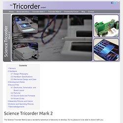
It's my pleasure to be able to share it with you. To introduce you to the Tricorder project, I'd like to begin with a story from the development of the very first Tricorder that I built. The first educational discoveries with the Tricorder came only moments after completing it, and walking about the workshop to "see what can't be seen". Notes on the 8051. Electronics Engineering Hotsheets - The EE Compendium. Geeks have feelings.
Attie.co.uk - Re-flashing an XBee Module. If you have ever managed to break your XBee module, then fear not!
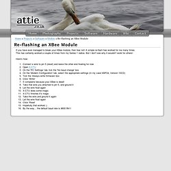
A simple re-flash has worked for me many times. This has certainly worked a couple of times from my Series 1 radios. But I don't see why it wouldn't work for others! HOW TO GET WHAT YOU WANT. Welcome to the KOBAKANT DIY Wearable Technology Documentation Workshops least likely scenario This workshop is part of a course at the Ernst Busch Hochschule in Berlin. It is only open to students in the departments of Spiel&&Objekt. Workshops soft sensors for soft bodies FURTHER_READING_WATCHING_LISTENING_ Elektronische Textilien als Material und Werkzeug_ Hannah Perner-Wilson, Irene Posch, 2020 “Welche Fasern leiten Strom?
Download Python. OpenPGP Public Keys Source and binary executables are signed by the release manager or binary builder using their OpenPGP key. Release files for currently supported releases are signed by the following: Release files for older releases which have now reached end-of-life may have been signed by one of the following: Anthony Baxter (key id: 0EDD C5F2 6A45 C816)Georg Brandl (key id: 0A5B 1018 3658 0288)Martin v. Löwis (key id: 6AF0 53F0 7D9D C8D2)Ronald Oussoren (key id: C9BE 28DE E6DF 025C)Barry Warsaw (key ids: 126E B563 A74B 06BF, D986 6941 EA5B BD71, and ED9D77D5) You can import a person's public keys from a public keyserver network server you trust by running a command like: gpg --recv-keys [key id] or, in many cases, public keys can also be found at keybase.io.
Gpg --verify Python-3.6.2.tgz.asc. Bone. Explore the high-performance, low-power world with the tiny, affordable, open-source Beagles. Putting Android, Ubuntu and other Linux flavors at your fingertips, the Beagle family revs as high as 1GHz with flexible peripheral interfaces and a proven ecosystem of feature-rich "Cape" plug-in boards. BeagleBone Black The benchmark for open hardware Linux computers. Get the workhorse 1GHz AM335x ARM® Cortex-A8 processor, expanded peripherals, low power consumption and open source software compatibility. Learn more » The Paleotechnologist - Modern Fun With Old-School Tech. Fpga4fun.com - Welcome. DIY Cellphone. An exploration into the possibilities for individual construction and customization of the most ubiquitous of electronic devices, the cellphone. By creating and sharing open-source designs for the phone’s circuit board and case, we hope to encourage a proliferation of personalized and diverse mobile phones.
Freed from the constraints of mass production, we plan to explore diverse materials, shapes, and functions.