
Everyone Tips Cap To Show RE2PECT For Retiring Yankee Legend Derek Jeter In This Great Tribute. Arduino Tutorial (LM35 Temp Sensor) HomePage. Foto por el A-Team Noticias 2011.07.06 Arduino Conectado (Arduino Hackathon en Campus Party Valencia 2011) 13 al 17 de julio de 2011. 2011.06.28 Arduino Virtualcamp (Hackaton de 48h.) 16 y 17 de julio de 2011. 2011.04.29 V Arduino Barcamp (Castellón de la Plana) 29, 30 de abril y 1 de mayo de 2011. 2011.02.11 Presentación, proyección y coloquio.
Playground - Arduino en Español - Wiki Comunitaria. Fotografía de alta resolución de una placa arduino Δ (Retoque de la fotografía de Nicholas Zambetti) Esta es la Wiki comunitaria de Arduino en Español.
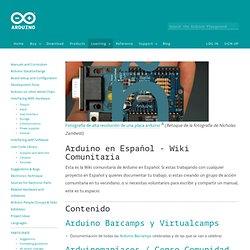
Si estas trabajando con cualquier proyecto en Español y quieres documentar tu trabajo, si estas creando un grupo de acción comunitaria en tu vecindario, o si necesitas voluntarios para escribir y compartir un manual, este es tu espacio. Tutoriales. StepperUnipolar. Learning Examples | Foundations | Hacking | Links This page shows two examples on how to drive a unipolar stepper motor.

These motors can be found in old floppy drives and are easy to control. The one we use has 6 connectors of which one is power (VCC) and the other four are used to drive the motor sending synchronous signals. The first example is the basic code to make the motor spin in one direction. It is aiming those that have no knowledge in how to control stepper motors. The prototyping board has been populated with a 10K potentiomenter that we connect to an analog input, and a ULN2003A driver.
Picture of a protoboard supporting the ULN2003A and a potentiometer. Stepper. Referencia del Lenguaje. PortManipulation. Reference Language | Libraries | Comparison | Changes Port registers allow for lower-level and faster manipulation of the i/o pins of the microcontroller on an Arduino board.
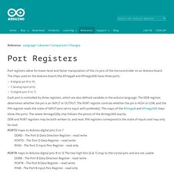
The chips used on the Arduino board (the ATmega8 and ATmega168) have three ports: B (digital pin 8 to 13) C (analog input pins) D (digital pins 0 to 7) Each port is controlled by three registers, which are also defined variables in the arduino language. The DDR register, determines whether the pin is an INPUT or OUTPUT. DDR and PORT registers may be both written to, and read. PORTD maps to Arduino digital pins 0 to 7 DDRD - The Port D Data Direction Register - read/write PORTD - The Port D Data Register - read/write PIND - The Port D Input Pins Register - read only.
Playground - BitMath. Note: This page was inspired by a conversation that took place in the Arduino forum.
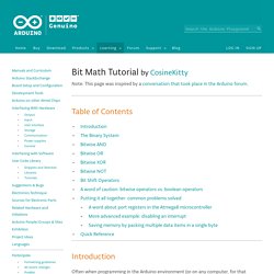
Table of Contents Introduction Often when programming in the Arduino environment (or on any computer, for that matter), the ability to manipulate individual bits will become useful or even necessary. Here are some situations where bit math can be helpful: Saving memory by packing up to 8 true/false data values in a single byte. <avr/interrupt.h>: Interrupts. Detailed Description Note: This discussion of interrupts was originally taken from Rich Neswold's document.
See Acknowledgments. Acordeon-arduino.png (Imagen PNG, 3300x2499 pixels) - Escala (25%) Instructables - Make, How To, and DIY. Arduino y bluetooth. Optical mouse hacking, part 1 « Department of New Computings. Arduino driver for the ADNS2610 follows the cut, along with sample implementation and a fairly straightforward Processing app to read the data.
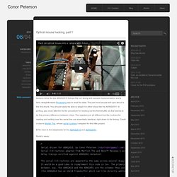
The part most people will care about is the first chunk. You should easily be able to adapt it to other chips like the ADNS2051. In porting, pay close attention to the procedure for reading out the framebuffer, as that seems to be the primary difference between chips. The registers are all different but the routines for reading and writing over the serial line are essentially identical, right down to the timing. Credit is due to Martijn Thé, whose serial routines I adapted for this little project. BTW, here’re the datasheets for the ADNS2610 and ADNS2051. The World Famous Index of Arduino & Freeduino Knowledge. Txapuzas electrónicas. Txapuzas electrónicas: PaperTeclado: Un teclado con una hoja impresa de papel. Introducción ¿Necesitas unos pulsadores para tu proyecto con un microcontrolador?
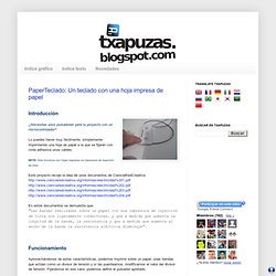
Lo puedes hacer muy fácilmente, simplemente imprimiendo una hoja de papel a la que se fijarán con cinta adhesiva unos cables. (16) Reutilizar el motor de un lector CDROM. Hoy tenemos un lector de CDROM para desarmar.
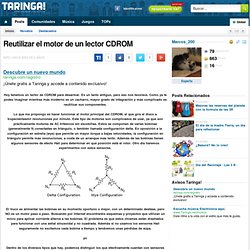
Es un tanto antiguo, pero eso nos favorece. Como ya te podes imaginar mientras más moderno es un cacharro, mayor grado de integración y más complicado es reutilizar sus componentes. Lo que me propongo es hacer funcionar el motor principal del CDROM, el que gira el disco a tropecientasmil revoluciones por minuto. How-To: Shrinkify Your Arduino Projects. Programming an ATtiny w/ Arduino. This tutorial shows you how to program an ATtiny45 or ATtiny85 microcontroller using the Arduino software and hardware. JeremyBlum.com. Tutorial 02 for Arduino: Buttons, PWM, and Functions. 03: Electrical Engineering Basics. 04: Analog Inputs. 05: Motors and Transistors. 06 : Serial Communication and Processing. 07: I2C Communication and Processing. 08: SPI Interfaces. ReacXion (Interactive Electronic Art) Build Log Part 4: Breadboard Prototype. Tutorial 09 for Arduino: Wireless Communication.
Tutorial 10 for Arduino: Interrupts and Hardware Debouncing. Tutorial 11 for Arduino: SD Cards and Datalogging. Tutorial 12 for Arduino: RFID Card Reading. Tutorial 13 for Arduino: Liquid Crystal Displays (LCDs) Tutorial 14 for Arduino: Holiday Lights and Sounds Spectacular! Tutorial 15 for Arduino: GPS Tracking. Downloadable Content - Tutorial 14 for Arduino: Lights and Sounds Holiday Special. TKJ Electronics » Arduino RGB LED Controller.