
Resistor ladder - Wikipedia. Build your own cellphone for $200. Electronic Circuits - Simple Circuits and Mini Projects.
Tidu020a. Enclosures. Battery Chargering Circuit. Intelligent NiCd/NiMH Battery Charger. Introduction As a handyman myself I have a certain amount of power tools.

The power source of cordless tools ranges from 3.6V to 18V and almost inevitably consists of Sanyo or Panasonic NiCd/NiMH cells, despite the actual brand of the power tool itself. Properly treated, these battery packs should be good for hundreds of charges and could potentially last many years. Recently I found my 2-year-old 9.6V cordless drill battery wouldn't perform to its rated capacity after charging. Unfortunately the battery packs are fairly expensive to replace, sometimes costing almost as much as the entire drill kit, if in fact you can purchase the batteries separately at all. 10 best IOT Hardware platforms - Gadgetronicx. IOT is growing rapidly and we are not far from days where our machines can interact with each other and act accordingly.

In fact we will be left behind if we don’t adapt or learn this amazing technology. Here is a list of 10 best IOT hardware platforms which will help us to learn and prototype IOT devices and stuffs. This list was compiled after seeking experts opinions, conducting polls, forum discussions and much more. Therefore it reflects the choice of many Embedded Programmers and designers. I believe this list will help to choose the perfect platform for you. Electricity F.A.Q. Power Supplies - Page 4 of 18. 24V SCR Battery Charger by Jim Keith | This is an extension of the earlier 12V SCR Battery Charger.
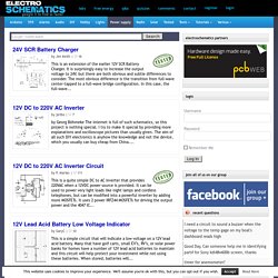
It is surprisingly easy to increase the output voltage to 24V, but there are both obvious and subtle differences to consider. Measuring Battery Voltage with an ADC > Measuring Battery Voltage with an ADC How to measure the voltage on a power source that is greater than the maximum rating of your ADC If you are using a battery powered device, it's often useful to be able to measure the current voltage level on the battery to estimate how much stored energy is left.
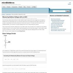
You may wish to alert the user if the charge level drops below a certain level, for example, or automatically shut the device off beyond a certain lower threshold. On the other end of the scale, if you are charging the battery, you may wish to cut off the charging process once a certain upper limit is reached. These measurements would all be relatively easy if your battery supply never exceeded 3.3V, for example, but many batteries do indeed exceed 3.3V, such as Lithium Polymer cells that typically go up to 4.2V when fully charged -- much too high to safely connect to an ADC line on your MCU.
4000 Logic IC's. Microcontroller Projects - DIY Electronics Circuits and Projects Based on Microcontrollers. About DorkbotPDX. DorkbotPDX is the Portland chapter of Dorkbot, people doing strange things with electricity.

We were founded in 2006 are now in a permanent (revolutionary) process of redefining ourselves and the logistics of this organization. We are a community of creative types who enjoy experimenting, finding art in technology and pushing the limits of whatever is in front of us. We meet on an regular, informal basis every other week, but you can find out more on our meetings page. General electronics circuit diagrams. Nintendo (NES) Electronic Circuit Schematic. Nintendo (NES) Schematic Schematics submitted by Cyberspike Return to the Schematic Archive.

What’s The Difference Between HBM, CDM, And MM Test? Electrostatic discharge (ESD) and electrostatic overstress (EOS) events can happen anywhere such as fabrication and assembly process areas, production testing environments, transportation, and field applications.

(See “Understanding ESD And EOS Failures In Semiconductor Devices”). EOS and ESD may be caused by the user’s application due to a transient, excessive supply current, poor grounding, low resistance path between supply voltage and ground, shorted pins, and internal damage of the circuit. The IC may eventually fail if it’s exposed to conditions beyond the datasheet specifications. EOS damage can’t be generated by the internal conditions of the component when operating within the datasheet specifications, so it occurs when abnormal conditions are present. Logic Signal Voltage Levels : Logic Gates. Logic gate circuits are designed to input and output only two types of signals: “high” (1) and “low” (0), as represented by a variable voltage: full power supply voltage for a “high” state and zero voltage for a “low” state.
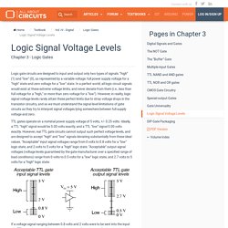
In a perfect world, all logic circuit signals would exist at these extreme voltage limits, and never deviate from them (i.e., less than full voltage for a “high,” or more than zero voltage for a “low”). However, in reality, logic signal voltage levels rarely attain these perfect limits due to stray voltage drops in the transistor circuitry, and so we must understand the signal level limitations of gate circuits as they try to interpret signal voltages lying somewhere between full supply voltage and zero. TTL gates operate on a nominal power supply voltage of 5 volts, +/- 0.25 volts. Ideally, a TTL “high” signal would be 5.00 volts exactly, and a TTL “low” signal 0.00 volts exactly.
74HC_HCT4017.pdf. Battery amp-hour, watt-hour and C rating tutorial. Recommended videos. Amplitude Modulation tutorial and AM radio transmitter circuit. What is an oscillator? Oscillator tutorial in HD! P-FET Reverse Voltage Polarity Protection Tutorial. What is a schottky diode? What is a zener diode? Class D Amplifier Tutorial! Operational Amplifier Tutorial & super microphone circuit. Textbook for Electrical Engineering & Electronics. Electronics I & II. Analog Devices is as passionate about educating the next generation of young circuit design engineers as it is about pioneering the next technological breakthrough.

The University Program is a platform where Analog Devices, working with leading educational institutions has created and deployed new hands on learning tools for the next generation of analog circuit design engineers. The University Program brings the analog signal processing technology the company has developed to the academic community in a way that is open and accessible to faculty and students in the form of analog design kits and analog components, online and downloadable software and teaching materials, online support, textbooks, reference designs and lab projects to enrich students’ education about analog circuits and their application to core engineering and physical science curricula.
Table of Content:Preface: 555 Timer IC. Audio, radio, sensors, digital electronics... SMD Adapters. BQ2002 Evaluation Module for NiCd/NiMH, Linear with -dV or Peak Voltage Detect - DV2002L2. The Basics of USB Battery Charging: A Survival Guide. Table of contentsIntroductionAn Array of Power SourcesDetecting the Source TypeUSB Connection TerminologyPort Detecting and Self-Enumerating ChargerAdding Port DetectionOther Charge StrategiesUSB 3.0"Cheating"—Noncompliant USB ChargingWrap Up Introduction.

Internet of Things Prototyping Hardware Round-up- Postscapes. A Current Sensing Tutorial-Part II: Devices. Building a Differential Amplifier : Operational Amplifiers - Electronics Textbook. An op-amp with no feedback is already a differential amplifier, amplifying the voltage difference between the two inputs. However, its gain cannot be controlled, and it is generally too high to be of any practical use. So far, our application of negative feedback to op-amps has resulting in the practical loss of one of the inputs, the resulting amplifier only good for amplifying a single voltage signal input. With a little ingenuity, however, we can construct an op-amp circuit maintaining both voltage inputs, yet with a controlled gain set by external resistors. If all the resistor values are equal, this amplifier will have a differential voltage gain of 1. The analysis of this circuit is essentially the same as that of an inverting amplifier, except that the noninverting input (+) of the op-amp is at a voltage equal to a fraction of V2, rather than being connected directly to ground.
Wave Bubble. Two Wavebubbles. Left is an earlier revision with the top removed and with external antennas. Right is v1.0 with internal antennas, fit into a pack of cigarettes. Penguin's Lab - High voltage,high energy and high temperatures. Welcome to Play-Hookey! Bipolar Junction Transistors. Bipolar Junction Transistors as Switches : Discrete Semiconductor Devices and Circuits Worksheets. Learning to mathematically analyze circuits requires much study and practice. Typically, students practice by working through lots of sample problems and checking their answers against those provided by the textbook or the instructor. Zener Diodes : Diodes and Rectifiers - Electronics Textbook. If we connect a diode and resistor in series with a DC voltage source so that the diode is forward-biased, the voltage drop across the diode will remain fairly constant over a wide range of power supply voltages as in Figure below (a).
According to the “diode equation” here, the current through a forward-biased PN junction is proportional to e raised to the power of the forward voltage drop. Because this is an exponential function, current rises quite rapidly for modest increases in voltage drop. Another way of considering this is to say that voltage dropped across a forward-biased diode changes little for large variations in diode current. In the circuit shown in Figure below (a), diode current is limited by the voltage of the power supply, the series resistor, and the diode’s voltage drop, which as we know doesn’t vary much from 0.7 volts.
Circuit Exchange International (CXI) Arduino Ultrasonic Proximity Sensor. Electronics Circuits Support: AUTO TURN-OFF BATTERY CHARGER. This charger for series-connected 4-cell AA batteries automatically disconnects from mains to stop charging when the batteries are fully charged. It can be used to charge partially discharged cells as well. The circuit is simple and can be divided into AC-to-DC converter, relay driver and charging sections. In the AC-to-DC converter section, transformer X1 steps down mains 230V AC to 9V AC at 750 mA, which is rectified by a full-wave rectifier comprising diodes D1 through D4 and filtered by capacitor C1 Regulator IC M317 (IC1) provides the required 12V DC charging voltage.
When you press switch S1 momentarily, the charger starts operating and the power-on LED1 glows to indicate that the charger is ‘on.’ The relay driver section uses pnp transistors T1, T2 and T3 (each BC558) to energise electromagnetic relay RL1. Mains is still available to the primary of the transformer through its normally open (N/O) contacts. In the charging section, regulator IC1 is biased to give about 7.35V. The Engineering Projects. Stumbleupon. Online Documentation for Altium Products. Datasheets, Electronic Components, Parts, Search. Electronics Concepts. Op-Amp Voltage and Gain Calculator. Next.gr. Audio, radio, sensors, digital electronics... Electronics Index. CircuitsArchive - Electronic Circuits Schematics. Operational amplifier applications.
This article illustrates some typical applications of operational amplifiers. Hobby projects - Simple electronic circuits. Computer microphones Learn how to interface electret and dynamic microphones to the standard computer sound card. Eng Sci 154 Home Page. Electrical Engineering and Computer Science. Final Year Project: Low Cost PC-Based Quad Channel Oscilloscope - Final Report. Electronics Demonstrations. Circuits in the Circuits Archive. Circuit Simulator Applet. 555 Timer Tutorials.
Freaklabs - Open Source Wireless - Feeding the Shark - Turning the Freakduino into a Realtime Wireless Protocol Analyzer with Wireshark. RF Communication Between Microcontrollers – Part I. RF Communication Between Microcontrollers – Part I Jul 07, 2009 Avinash RF 28 In many situations a communication link between to devices becomes essential. This communication can be wired or wireless. USB Made Simple. Mike's Electric Stuff. Build the BASIC SPY TRANSMITTER - Page 1 of 16. Build the 2 transistor Spy Transmitter. Dc-dc converters, switching mode power supply, power electronics, Pspice. Bipolar Junction Transistors.
AVR projects and AVR Butterfly gcc port. By Martin THOMAS G.d.W. Bipolar junction transistors as switches : Worksheet. Analog Innovations. Capacitor Voltage Change. Capacitance. All About Circuits : Free Electric Circuits Textbooks. Electronic Circuits on Circuit Exchange International (CXI) Open Circuit Design. ECE 3050 - Analog Electronics. Projects.