
SRedmond-com Disk Turbine Generator Page 4. April 16, 2003 Cont'd.
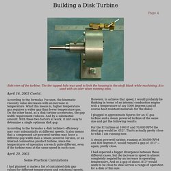
According to the formulas I've seen, the kinematic viscosity value decreases with an increase in temperature. What this means is, higher temperature gas requires a wider gap than lower temperature gas. On the other hand, as a disk turbine accelerates, the gap width requirement reduces. And by a substantial amount. With these two factors at work, it isn't easy to determine a single optimum disk gap. According to the formulas a disk turbine's efficiency may vary substantially at different speeds. April 20, 2003 Some Practical Calculations I had planned to make a list of calculated disk gap values for different temperatures and rotational speeds, but when I actually plugged in the numbers an interesting thing happened. The formula I used was adapted from a paper by Glen A.
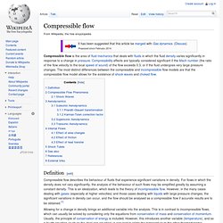
Pi*SQRT(1376*Kinematic Viscosity/RPM)) for kinematic viscosity measured in sq. ft. HeatEnginesVol 2 Chapter 8 RS. De Laval nozzle. Diagram of a de Laval nozzle, showing approximate flow velocity (v), together with the effect on temperature (T) and pressure (p) A de Laval nozzle (or convergent-divergent nozzle, CD nozzle or con-di nozzle) is a tube that is pinched in the middle, making a carefully balanced, asymmetric hourglass shape.
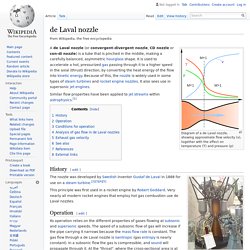
It is used to accelerate a hot, pressurized gas passing through it to a higher speed in the axial (thrust) direction, by converting the heat energy of the flow into kinetic energy. Because of this, the nozzle is widely used in some types of steam turbines and rocket engine nozzles. It also sees use in supersonic jet engines. History[edit] The nozzle was developed by Swedish inventor Gustaf de Laval in 1888 for use on a steam turbine.[2][3][4][5] Operation[edit] Its operation relies on the different properties of gases flowing at subsonic and supersonic speeds.
Conditions for operation[edit] FLYING STEAM ENGINES 7. FLYING STEAM ENGINES - Generation the Steam Conventional boilers ln their simplest form a boiler is a round tank of water with a fire underneath and in the case of my first engine (designed in 1967 by David Parker) it is little more than that.
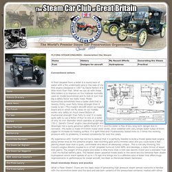
What we can do with these little boilers is to improve on the material normally used on model locomotives and to look at just how big a safety factor we really need. Model locomotives sometimes have a boiler shell that is twenty, thirty, even forty times stronger than it needs to be! ! My experience with 'Comet' has led me to believe that it is perfectly feasible to build a model speed boat engine along similar lines as the airborne engine.
Small monotube theory and practice What is Flash Steam? I have no complaint about Skylark, I launched her in the Chichester Ship Canal in April 2003 and everything operated much as the previous owner had said it should except, try as I might all I could get was 25psi and a slow walking pace. E.T. E.T. Boundary Layer (Tesla) Turbine Page. The Tesla Boundary Layer Turbine Well...it sure does spin fast...real fast!
(Click on thumbnails to view full size images.) Please check the licensing link below for use and licensing information for the contents of this web site. Compressible flow. Compressible flow is the area of fluid mechanics that deals with fluids in which the fluid density varies significantly in response to a change in pressure.
Compressibility effects are typically considered significant if the Mach number (the ratio of the flow velocity to the local speed of sound) of the flow exceeds 0.3, or if the fluid undergoes very large pressure changes. The most distinct differences between the compressible and incompressible flow models are that the compressible flow model allows for the existence of shock waves and choked flow. Definition[edit] Compressible flow describes the behaviour of fluids that experience significant variations in density. Compression via Tesla turbines. Converging Diverging Nozzle. Instructions.
Tesla's Fuelless Generator. Having a bit of Trouble with Tesla Turbine [Archive] - The Home Shop Machinist & Machinist's Workshop Magazine's BBS. Ah yes, welcome to the exciting and challenging world of the Tesla turbine.
![Having a bit of Trouble with Tesla Turbine [Archive] - The Home Shop Machinist & Machinist's Workshop Magazine's BBS](http://cdn.pearltrees.com/s/pic/th/machinist-workshop-magazine-56086017)
:D At a quick glance the Tesla turbine is a deceptively simple device, an engine with only one moving part. How difficult can that be to make? Well that is until you try to build one. Of course many have built turbines that worked, however the real trick is to not only make it run, but run efficiently! If you wanted to build a standard gas engine you could go to a library and look up all the design information you need with Tesla turbine you will find that there is precious little really good design data available. Tesla Turbine - Three Key Efficiency Points. Written by Phoenix Navigation According to Nikola Tesla, the Three key efficiency points of his turbine are: the inlet nozzledisk geometrythe outlet nozzle Disk Geometry Disk geometry is a simple matter of using the right material with the right spacing and the right number position of spacers, or sandwiched elements.

Starting with materials, use a good high strength stainless steel like 361 or 461 with as bright a polish as possible. Space the disks anywhere from 0.032 inch to 0.125 inch, with the narrow spacing developing higher torque, lower horsepower -- and conversely. Spacers should consist of a star type for the center, with 0.5 inch round washers placed at the mid and outer periphery positions.