
Operating Service Manual Analogic Data Precision 2020 by JBTech. SCIDYNE® Corporation. The ADIO-104 is an 8-bit analog and digital input/output module designed to satisfy a broad range of applications.
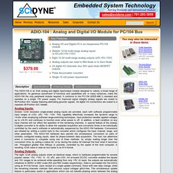
Its generous assortment of functions and capabilities will, in many instances, make the ADIO-104 the only peripheral module required. It conforms to the PC/104 (IEEE-996.1) standard and operates on a single +5V power supply. For improved signal integrity analog signals are routed to 50-Position IDC header featuring alternating grounds signals. All digital I/O connections are routed to a separate 26-Position IDC header. Analog Inputs: Sixteen 12-bit resolution single-ended analog inputs are provided, each with software programmable input ranges of ±10V, ±5V, +5V, +10V. Analog Outputs: The eight 12-bit analog outputs share an identical range, which is hardware programmable for several popular values: +5V, +10V, -5, -10, ±5V, and ±10V. Digital I/O: The ADIO-104 features 24 digital I/O channels in the form of three 8-bit ports. How to program the Touch Board for On Board MIDI Mode. Step 4 Upload MIDI piano code We now need to upload the MIDI piano code to the Touch Board.

Firstly, if you haven’t already completed our Setting up Arduino with your Touch Board tutorial, please do that before continuing. Once this is done, plug the Touch Board into the computer via the USB cable. Make sure that the power switch on the board is set to ON. File→Sketchbook→Touch Board Examples→Midi_Piano Ensure that Bare Conductive Touch Board is selected under Tools→Board and that the correct serial (CU) port is selected under Tools→Port. With all of the correct settings selected, click File→Upload to push the code to the Touch Board.
With your Touch Board still connected to the computer test the program by plugging in a pair of headphones or a self powered speaker and run your finger over the electrodes. If there are any issues check that the solder connections are properly bridging the two pads mentioned in Step 2 above. Internet of things. Better SPI Bus Design in 3 Steps. Most Arduino SPI tutorials show this simple but poor SPI bus design: A much better SPI bus design can prevent conflicts. 3 simple improvements are needed: Use pullup resistors on all chip select signals.Verify tri-state behavior on MISO: use a tri-state buffer chip if necessary.Protect bus access with SPI.beginTransaction(settings) and SPI.endTransaction().
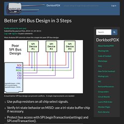
Click "Read more" for details on these 3 steps. Step 1: Pullup Resistors for Chip Select & Reset Signals When multiple SPI devices are used, and especially when each is supported by its own library, pullup resistors are needed on the chip select pins. Without a pullup resistor, the second device can "hear" and respond to the communication taking place on the first device, if that second device's chip select pin is not pulled up. A simpe workaround for devices without pullup resistor involves adding code at the beginning of setup.
21952b.pdf. Solution-VS1053 - Ogg Vorbis / MP3 / AAC / WMA / FLAC / MIDI Audio Decoder / Encoder Chip. Adafruit Audio FX Mini Sound Board - WAV/OGG Trigger - 2MB Flash ID: 2342 - $14.95. Would you like to add audio/sound effects to your next project, without an Arduino+Shield?
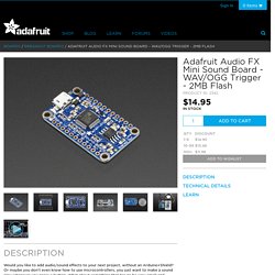
Or maybe you don't even know how to use microcontrollers, you just want to make a sound play whenever you press a button. What about something that has to be very small and portable? You are probably feeling a little frustrated: it's been very hard to find a simple, low cost audio effects trigger that is easy to use and does not require any programming Don't get me wrong, I love the MP3 Music Maker shield and the Audio FX Sound Board + 2x2W Amp. And our Wave Shield is a dependable classic. The Sound Board has a lot of amazing features that make it the easiest thing ever: No Arduino or other microcontroller required! What do we mean by trigger effects? We designed this board specifically for people who wanted to make props, costumes, toys, and other small portable projects.
Serial library rxtx v2.2pre5. Protocol Communication. Ploytec GmbH - USB 3.0 Audio and more. Mbsd_l16. SPI slave devices.